
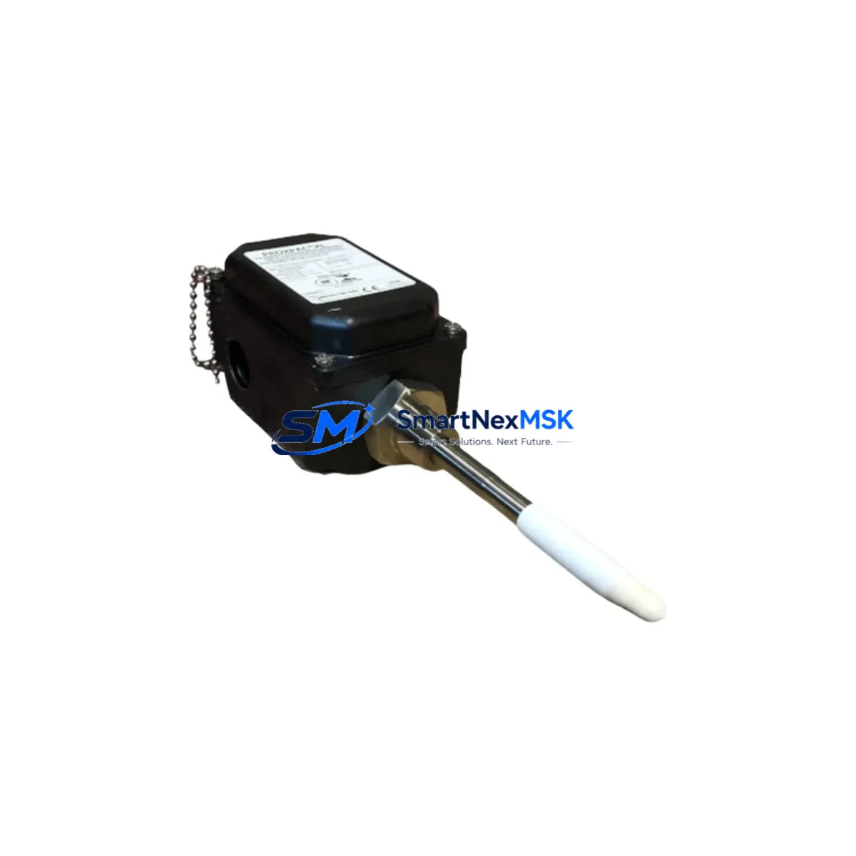
Bently Nevada 330881-28-10-148-03-02 Retrofit-Ready Proximity Transducer for PROXPAC XL Control Systems
The Bently Nevada 330881-28-10-148-03-02 is a retrofit-ready 8mm proximity transducer assembly designed for direct compatibility with PROXPAC XL vibration monitoring systems. As legacy Bently Nevada 3300 Series installations reach end-of-service milestones, plant engineers and reliability teams increasingly require verified drop-in replacements that preserve existing wiring, conditioner calibration, and system alarm setpoints without triggering a full platform migration. This assembly addresses that need precisely — delivering OEM-equivalent signal output, gap voltage characteristics, and mechanical dimensions that align with the original PROXPAC XL installation envelope.
The 330881-28-10-148-03-02 is specified with a 28-inch (711 mm) armored extension cable, 10-32 UNF threaded tip, 148-inch (3759 mm) interconnect cable, and a standard 02 connector termination. These parameters are critical when retrofitting into existing conduit runs and junction boxes where cable routing cannot be easily modified. Before installation, engineers should verify the existing 3300 XL proximitor — typically the 330180 or 330185 series — remains in service, as the transducer and proximitor must be used as a matched system to maintain calibrated sensitivity of 200 mV/mil (7.87 V/mm).
Upgrade Compatibility Table
| Parameter | 330881-28-10-148-03-02 | Retrofit Notes |
|---|---|---|
| Tip Diameter | 8 mm | Verify existing probe bore; no machining required for standard 3300 XL mounts |
| Extension Cable Length | 28 in (711 mm) | Match to existing conduit stub length before ordering |
| Interconnect Cable Length | 148 in (3759 mm) | Confirm routing distance to proximitor enclosure |
| Connector Type | 02 (standard BNC-compatible) | Compatible with 330180 and 330185 proximitor input ports |
| Output Sensitivity | 200 mV/mil | Recalibrate gap voltage to –10.0 VDC at 50 mil (1.27 mm) nominal gap |
| Supply Voltage | –24 VDC (nominal) | Confirm barrier or proximitor supply rail capacity before hot-swap |
| Communication Compatibility | Analog 4–20 mA / voltage output via proximitor | No protocol change required; integrates with existing 3500 rack I/O cards |
| Replacement Recommendation | Direct replacement for 330881 series | Cross-reference 330875, 330876, 330877 for alternate cable configurations |
| Commissioning Focus | Gap voltage, polarity, and alarm setpoint verification | Use Bently Nevada ADRE or System 1 software for post-installation trending |
| Warranty | 12 Months | Covered from date of shipment; includes DOA replacement |
Retrofit Planning for Existing Automation Systems
Successful integration of the 330881-28-10-148-03-02 into an aging plant automation environment requires a structured pre-outage assessment. Begin by auditing the existing 3500 Series monitoring rack to confirm available channel slots and I/O module assignments. The 3500/42M Proximitor I/O Module is the most common interface card in legacy installations and accepts the transducer signal directly through the matched 330180 proximitor. If the rack also houses a 3500/22M Transient Data Interface or a 3500/92 Communication Gateway, verify that channel mapping and Modbus or OPC-DA tag assignments remain intact after the transducer swap.
For plants running a distributed control system such as a Honeywell Experion PKS or Emerson DeltaV, the 3500 rack typically communicates via a dedicated serial or Ethernet link to the DCS historian. Confirm that the 3500 rack’s communication module — often a 3500/92 or 3500/93 — does not require a firmware update when the transducer channel is reconfigured. In installations where the HMI faceplate displays gap voltage trends, update the engineering unit scaling in the HMI tag database to reflect the new transducer’s calibration certificate values before returning the machine to service.
Wiring adaptation is straightforward for most retrofits. The 330881-28-10-148-03-02 uses a standard coaxial signal path from transducer tip through the armored extension to the proximitor, then a shielded twisted-pair interconnect to the 3500 rack terminal block. Inspect the existing terminal block for corrosion or loose ferrules, and replace the 3500 rack’s TB connector if contact resistance exceeds 0.5 ohm. Where Zener barriers or galvanic isolators are installed in the signal path for hazardous-area compliance, verify that the barrier’s working voltage and capacitance limits remain within the transducer system’s specification.
Plants upgrading from the older 7200 Series proximity system to the 3300/PROXPAC XL platform will also need to address mounting thread differences — the 7200 Series used a 3/8-24 UNF thread, while the 330881 uses 10-32 UNF — requiring a probe holder adapter or re-machined bracket. In these cross-generation upgrades, the 330130 Proximity Transducer System or the 330500 Proximity Transducer may serve as intermediate reference points for dimensional verification. Additionally, confirm that the existing proximitor power supply — whether a dedicated 24 VDC rail or a shared instrument bus — can sustain the additional current draw without affecting adjacent channels on the 3500/42M module.
Downtime Control During System Migration
Minimizing unplanned downtime during a proximity transducer replacement is achievable with disciplined pre-outage preparation. The recommended approach is a cold-swap during a scheduled maintenance window, with the machine de-energized and the 3500 rack placed in bypass mode to suppress spurious alarms during the swap interval. Before disconnecting the existing transducer, document the current gap voltage reading and alarm setpoints from the 3500 rack’s front-panel display or from System 1 software, so that post-installation verification has a clear acceptance baseline.
Once the 330881-28-10-148-03-02 is installed and the gap is set to the nominal –10.0 VDC reading, perform a static calibration check using a precision DC voltmeter at the proximitor output terminals before reconnecting to the 3500 rack. This step isolates any wiring or connector fault before the rack is taken out of bypass. Re-enable the rack channel, confirm that the System 1 or ADRE trending display shows a stable gap voltage within ±0.5 VDC of the pre-swap baseline, and verify that the Keyphasor reference signal — if present on an adjacent 3500/25 Keyphasor Module — is still correctly phased. Only after these checks should the machine be returned to normal operating speed and the bypass mode cleared.
For critical rotating equipment where even a brief monitoring gap is unacceptable, consider a parallel installation strategy: mount the new 330881-28-10-148-03-02 in a spare probe port (if available) and trend both channels simultaneously for one full operating cycle before decommissioning the legacy transducer. This approach preserves continuous vibration data and allows direct comparison of old and new transducer outputs to confirm calibration equivalence before the final cutover.
Retrofit Support FAQ
Q: Is the 330881-28-10-148-03-02 a direct drop-in replacement for the original PROXPAC XL transducer?
A: Yes, for installations using the standard 8mm tip, 28-inch extension, and 148-inch interconnect configuration. Verify the connector type (02) and confirm the matched proximitor model (330180 or 330185) is retained. No re-wiring of the 3500 rack terminal block is required in most cases.
Q: What commissioning steps are mandatory after installation?
A: Set the transducer gap to achieve –10.0 VDC ±0.5 VDC at the proximitor output. Verify alarm setpoints in the 3500 rack configuration software. Confirm Modbus or OPC tag values are updating correctly in the DCS or historian. Document the as-left gap voltage on the maintenance record.
Q: Does this unit ship pre-tested?
A: Yes. Each 330881-28-10-148-03-02 unit undergoes functional output verification and continuity testing prior to shipment. A test report is available upon request. The unit is covered by a 12-month warranty from the date of shipment, including DOA replacement at no additional cost.
Q: What if my cable lengths differ from the 28-inch / 148-inch specification?
A: Bently Nevada’s 330881 series is available in multiple cable length configurations. Cross-reference the 330875, 330876, 330877, and 330880 part numbers for alternate extension and interconnect lengths. Contact our sales team with your existing part number and we will confirm the correct retrofit SKU for your installation.
© 2026 SMARTNEXMSK. All rights reserved.
Original Source: https://smartnexmsk.com
Contact: [email protected] | +86 18259474341



