
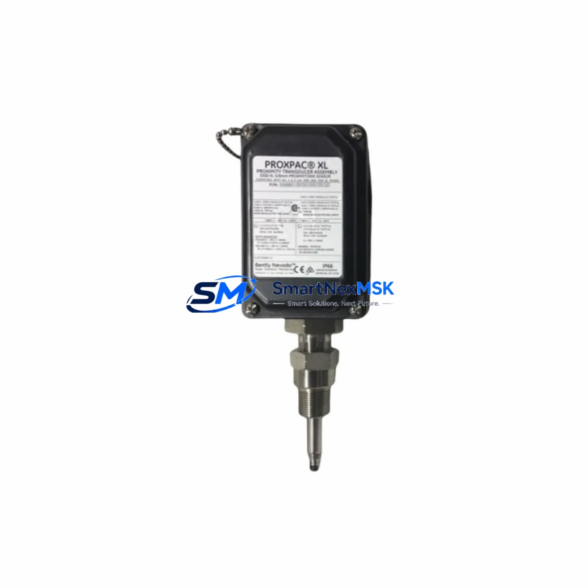
Bently Nevada 330881-BR-04-85-03-02 Retrofit-Ready Proximity Transducer for 3300 XL Control Systems
The Bently Nevada 330881-BR-04-85-03-02 is a retrofit-ready proximity transducer assembly engineered for seamless integration into legacy 3300 XL PROXPAC vibration monitoring systems. As aging 3300 Series installations approach end-of-support milestones, plant engineers and reliability teams increasingly require verified drop-in replacements that preserve existing wiring, signal conditioning, and monitor compatibility — without forcing a full platform migration. This unit is stocked, tested, and shipped with a 12-month warranty to support both emergency breakdown recovery and planned system modernization projects.
The 330881-BR-04-85-03-02 is a complete PROXPAC assembly combining an 8 mm proximity probe, extension cable, and Proximitor sensor into a single matched set. The assembly is calibrated for use with the Bently Nevada 3300 XL monitor series, including the 3300/16 and 3300/20 rack-mounted monitors, and is compatible with standard -24 VDC Proximitor power supplies. The output signal range, sensitivity (200 mV/mil), and gap voltage characteristics are factory-verified to match OEM specifications, ensuring that existing vibration alarm setpoints, danger thresholds, and Keyphasor references remain valid after replacement without requiring recalibration of the monitor card.
Upgrade Compatibility Table
| Parameter | 330881-BR-04-85-03-02 (This Unit) | Retrofit Notes |
|---|---|---|
| Probe Diameter | 8 mm | Matches standard 3300 XL PROXPAC bracket bore; no mechanical modification required |
| Extension Cable Length | 5 m (standard) | Verify existing conduit run; extension cables are field-replaceable if routing differs |
| Proximitor Supply Voltage | -24 VDC nominal | Compatible with existing 3300 XL power distribution; check terminal block polarity before energizing |
| Output Sensitivity | 200 mV/mil (7.87 V/mm) | Matches OEM calibration; alarm setpoints in 3300/16 or 3300/20 monitors remain valid |
| Gap Voltage (nominal) | -10.0 VDC at 50 mil (1.27 mm) | Verify gap with oscilloscope or Bently Nevada gap tool before final commissioning |
| Monitor Compatibility | 3300 XL 16/20, 3500/42, 3500/45 | Confirm channel configuration in rack; 3500 Series may require I/O module verification |
| Communication Protocol | Analog 4–20 mA / voltage output | No protocol migration required; signal passes through existing 3300 XL I/O termination |
| Installation Interface | Standard PROXPAC connector | Direct plug-in replacement; no adapter or wiring harness modification needed |
| Warranty | 12 Months | Covers manufacturing defects; includes pre-shipment functional test report |
Retrofit Planning for Existing Automation Systems
Replacing the 330881-BR-04-85-03-02 in an operating plant requires a structured approach that accounts for both the mechanical installation and the downstream signal chain. Before removing the existing PROXPAC assembly, engineers should document the current gap voltage reading at the Proximitor output terminal — typically accessible at the 3300 XL I/O termination module or the field junction box — and record the vibration baseline values displayed on the associated 3300/16 or 3300/20 monitor card. These reference values are essential for post-installation verification.
The replacement process begins at the field end. After isolating the machine and confirming zero-energy state, the probe tip is withdrawn from the bracket, the extension cable is disconnected at the field junction, and the Proximitor sensor is removed from its mounting bracket. The new 330881-BR-04-85-03-02 assembly is installed in reverse order. Pay particular attention to the terminal block wiring at the Proximitor output: the shield drain wire must be grounded at one end only (typically at the monitor rack end) to avoid ground loops that can introduce noise into the vibration signal.
At the rack end, the signal terminates at the 3300 XL I/O module or, in upgraded installations, at a 3500 Series I/O module such as the 3500/42 or 3500/45 position monitor. If the plant has partially migrated from the 3300 platform to the 3500 platform, verify that the channel configuration in the 3500 rack matches the probe type and sensitivity of the new assembly. The 3500 rack backplane and associated 3500/01 rack interface module must be configured to accept the -24 VDC Proximitor supply and the 200 mV/mil output characteristic.
For plants operating mixed-generation control architectures — where a DCS such as an Emerson DeltaV or a Honeywell Experion PKS receives vibration data from the 3300 or 3500 monitor via Modbus RTU or OPC — no changes to the communication layer are required when replacing a like-for-like PROXPAC assembly. The monitor’s analog output or serial communication card continues to transmit the same engineering-unit values to the DCS historian and alarm management system. However, if the retrofit is part of a broader upgrade that includes replacing the 3300 XL communication gateway with a 3500/92 communication gateway module, the Modbus register map and baud rate settings must be re-verified against the DCS I/O configuration.
Plants that also operate Keyphasor modules — such as the 3500/25 or the legacy 3300 Keyphasor monitor — should confirm that the phase reference signal is unaffected by the PROXPAC replacement. The Keyphasor probe is a separate assembly and is not part of the 330881-BR-04-85-03-02 kit, but its gap voltage and signal integrity should be verified during the same maintenance window to avoid a second outage. Similarly, if the machine train includes thrust position probes monitored by a 3500/45 or 3300/65 thrust monitor, those channels should be reviewed for alarm setpoint consistency after the radial vibration probe replacement is complete.
For sites where the control room uses a Bently Nevada System 1 software platform for machinery health monitoring, the asset configuration database should be updated to reflect the new probe serial number and calibration date. System 1 stores probe sensitivity and gap calibration data per asset, and an outdated entry can cause the software to flag false calibration warnings during the next scheduled data collection cycle.
Downtime Control During System Migration
Minimizing unplanned downtime during a PROXPAC replacement requires pre-staging all components before the maintenance window opens. The 330881-BR-04-85-03-02 assembly should be bench-tested prior to installation: connect the Proximitor to a -24 VDC bench supply, position a steel target at the nominal gap distance, and verify that the output voltage falls within the expected range (-9.5 to -10.5 VDC at 50 mil). This pre-shipment functional test is included with every unit shipped from our facility, and the test report is provided with the delivery documentation.
To protect the original program logic and control continuity during the replacement, the associated 3300 XL or 3500 monitor should be placed in bypass mode before the probe is removed. Bypass mode suppresses the vibration alarm outputs to the safety system and DCS, preventing a spurious trip during the period when the probe is disconnected and the Proximitor output is at rail voltage. The bypass command is typically issued from the monitor front panel or, in networked installations, from the System 1 operator interface. Confirm with the control room that the bypass is active and acknowledged before proceeding with field work.
Once the new assembly is installed and the gap is set, restore the monitor from bypass and observe the vibration reading for a minimum of five minutes at operating speed before re-enabling the alarm outputs. Compare the live vibration amplitude and phase angle against the pre-replacement baseline. A deviation of more than 10% in amplitude or 5° in phase angle warrants further investigation before the machine is returned to full load. This structured commissioning sequence — pre-test, bypass, replace, gap-set, restore, verify — typically allows a trained technician to complete the replacement within a two-hour maintenance window, keeping production impact to a minimum.
Retrofit Support FAQ
Q1: Is the 330881-BR-04-85-03-02 a direct drop-in replacement for the original Bently Nevada part?
Yes. The assembly is manufactured to match the OEM mechanical dimensions, electrical specifications, and output characteristics of the original 330881-BR-04-85-03-02. No adapter, wiring modification, or monitor reconfiguration is required for a like-for-like replacement in a 3300 XL PROXPAC system. A pre-shipment functional test report is included with each unit.
Q2: What wiring checks should be performed before energizing the new Proximitor?
Verify terminal polarity at the field junction box and at the I/O termination module in the monitor rack. Confirm that the shield drain wire is grounded at the rack end only. Check that the supply voltage at the Proximitor terminals is within the -18 to -26 VDC operating range before connecting the probe. Incorrect polarity or an out-of-range supply voltage will damage the Proximitor and void the warranty.
Q3: Can this assembly be used with the Bently Nevada 3500 Series monitors?
Yes, with configuration verification. The 330881-BR-04-85-03-02 is compatible with 3500/42 and 3500/45 monitor channels configured for 8 mm probes with 200 mV/mil sensitivity. Confirm the channel configuration in the 3500 rack software (Rack Configuration Software, RCS) matches the probe parameters before energizing. No hardware modification to the 3500 I/O module is required.
Q4: What does the 12-month warranty cover, and what is the claims process?
The 12-month warranty covers manufacturing defects in materials and workmanship from the date of shipment. It does not cover damage resulting from incorrect installation, reversed polarity, mechanical impact, or operation outside the specified voltage range. To initiate a warranty claim, contact [email protected] with the order number, unit serial number, and a description of the fault. A replacement unit or full refund will be processed within 5 business days of fault confirmation.
© 2026 SMARTNEXMSK. All rights reserved.
Original Source: https://smartnexmsk.com
Contact: [email protected] | +86 18259474341



