
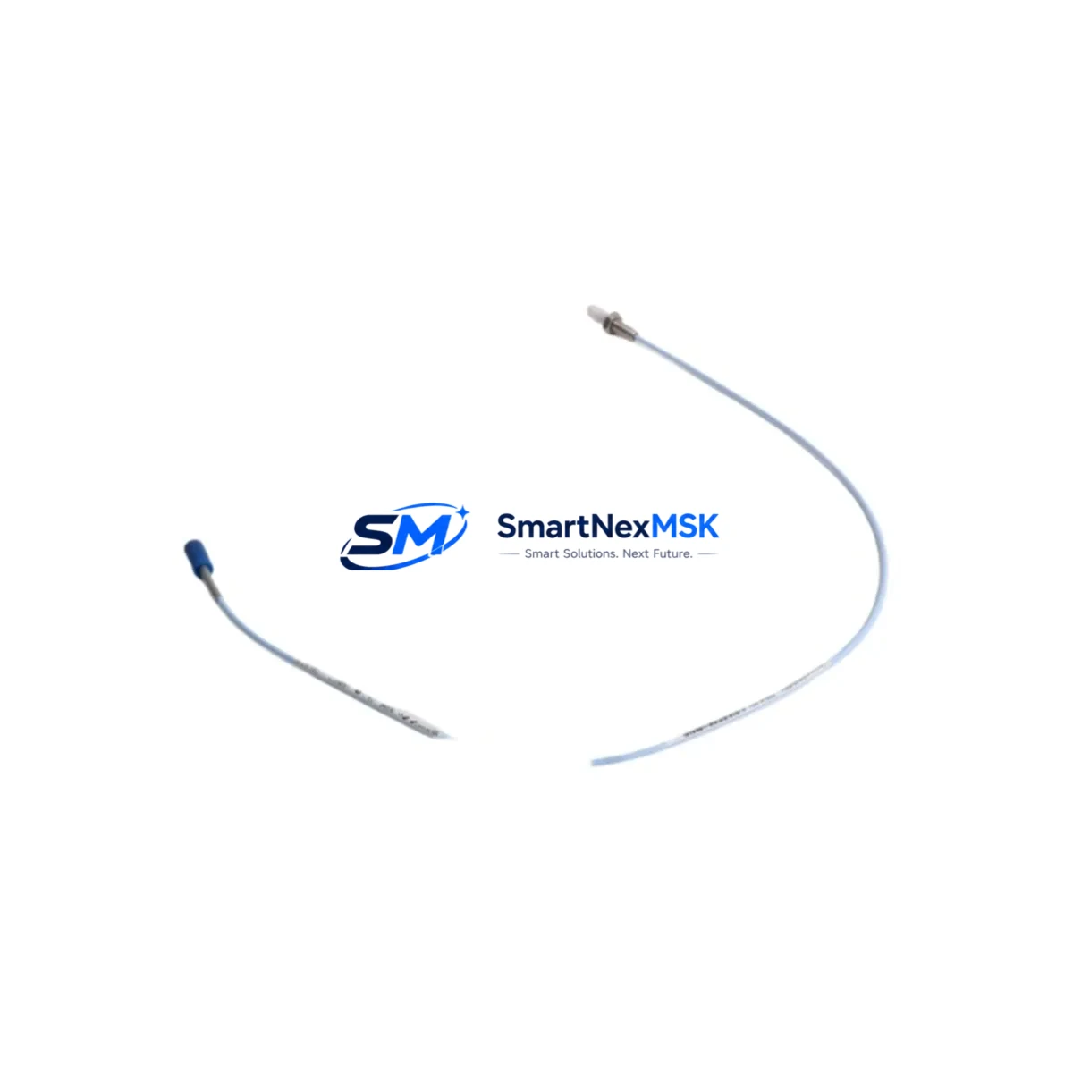
Bently Nevada 330901-00-32-05-02-05 Retrofit-Ready Velomitor for 3300 Series Control Systems
The Bently Nevada 330901-00-32-05-02-05 Velomitor Velocity Transducer is a precision seismic velocity sensor engineered for direct retrofit into existing Bently Nevada 3300 Series machinery protection systems. As legacy 3300 XY proximity systems approach end-of-life and OEM support windows close, plant engineers and reliability teams increasingly rely on this model as a verified drop-in replacement that preserves existing wiring infrastructure, terminal block assignments, and monitor channel configurations — eliminating the need for costly panel redesigns or full system overhauls.
This transducer delivers a velocity output signal fully compatible with the Bently Nevada 3300/16 Dual Velocity Monitor and the 3300/55 Dual Velocity Monitor, allowing seamless integration without reprogramming monitor setpoints or recalibrating alarm thresholds. The 330901-00-32-05-02-05 variant features a 32-inch (813 mm) integral cable, 5-pin MIL-C-5015 connector, and a sensitivity of 100 mV/in/s (4 mV/mm/s), matching the original factory specification for the 3300 XY Series installation envelope.
Upgrade Compatibility Table
| Parameter | Detail |
|---|---|
| SKU / Part Number | 330901-00-32-05-02-05 |
| Compatible Monitor | Bently Nevada 3300/16, 3300/55 Dual Velocity Monitor |
| Replaces / Supersedes | 330901-00-32-05-02-00, 330901-00-32-05-02-CN (legacy variants) |
| Output Signal | Velocity (mV/in/s), passive seismic |
| Sensitivity | 100 mV/in/s ± 5% |
| Cable Length | 32 inches (813 mm) integral |
| Connector Type | 5-pin MIL-C-5015 (compatible with existing field wiring) |
| Mounting Interface | 1/4-28 UNF threaded stud (standard 3300 Series footprint) |
| Communication / Protocol | Analog passive — no protocol migration required |
| Rack / Backplane Compatibility | 3300 Series rack, 3500 Series rack (with adapter) |
| Installation Requirement | Verify terminal block polarity; no address configuration needed |
| Commissioning Note | Confirm gap voltage and sensitivity at monitor front panel after installation |
| Warranty | 12 Months from date of shipment |
Retrofit Planning for Existing Automation Systems
Successful retrofit of the 330901-00-32-05-02-05 into an operating plant environment requires a structured pre-outage review. Before scheduling the changeover, engineers should pull the existing loop drawing to confirm the terminal block wiring sequence at the 3300/16 or 3300/55 monitor input card. The original two-wire passive connection — typically landed on TB1 terminals — carries over directly to the replacement unit without modification, provided the field cable is intact and insulation resistance is within specification.
In installations where the 3300 Series rack also houses a 3300/20 Keyphasor Module or a 3300/46 Tachometer Module, the Keyphasor signal reference must remain undisturbed during the transducer swap. Technicians should isolate only the velocity channel pair and leave adjacent module wiring untouched. If the control cabinet also contains a 3300/25 Overspeed Detection Module, confirm that the overspeed trip logic is bypassed or placed in bypass mode before removing the old transducer to prevent spurious trips during the open-circuit interval.
For plants running a hybrid architecture — where the 3300 Series rack feeds a System 1 Condition Monitoring platform or a third-party DCS via a 3300/93 Communication Gateway — verify that the gateway’s channel mapping table references the correct physical slot address. The 330901-00-32-05-02-05 does not alter the monitor’s slot address or channel number, so no gateway reconfiguration is required in a like-for-like swap. However, if the retrofit is part of a broader migration from a 3300 Series rack to a 3500 Series rack, the 3500/42M Velocity Monitor module will require a new I/O module and terminal block adapter, and the System 1 database will need a channel reassignment.
Where the plant’s control philosophy includes HMI faceplate displays driven by the monitor’s relay outputs, confirm that the HMI tag database references the correct relay module — typically a 3300/32 Relay Module — and that alarm setpoints are re-entered after any monitor replacement. If the site uses a 3300/10 Power Supply Module to feed the rack, verify that the supply’s current budget accommodates the replacement transducer’s passive load, which is negligible but should be documented in the panel schedule for future reference.
All replacement units are function-tested and loop-calibrated prior to shipment. Stock is maintained for immediate dispatch, supporting both planned turnaround outages and emergency breakdown scenarios. 12-month warranty coverage begins from the date of shipment.
Downtime Control During System Migration
Minimizing unplanned downtime during a Velomitor replacement begins with pre-staging the 330901-00-32-05-02-05 on the bench and verifying its open-circuit sensitivity using a calibrated shaker or signal simulator before the machine is taken offline. This pre-verification step eliminates the risk of discovering a defective unit after the old transducer has already been removed from the bearing housing.
During the physical swap, the existing field cable — typically a Bently Nevada 330130 or 330140 Series extension cable — should be inspected for jacket damage, connector pin corrosion, and continuity. If the extension cable is being retained, clean the MIL-C-5015 connector pins and apply a light coat of dielectric grease before mating with the new transducer. This step is frequently overlooked but is a common source of intermittent signal faults that appear only under vibration.
Once the replacement transducer is installed and the monitor channel is brought back online, confirm the DC gap voltage at the monitor front panel (or via the System 1 interface) before releasing the machine to operations. The gap voltage for a passive Velomitor is not applicable in the same way as a proximity probe, but the monitor’s OK relay status and the channel’s dynamic signal should be verified against baseline readings from the previous transducer. If the site maintains a vibration baseline database, update the reference spectrum immediately after commissioning to reflect the new transducer’s installed sensitivity.
For critical machinery where continuous monitoring is contractually required, consider using a portable data collector — such as a CSI 2140 or equivalent — to maintain vibration surveillance on the adjacent bearing during the brief monitoring gap. This approach preserves the condition monitoring record and satisfies most reliability program audit requirements without requiring a full system bypass.
Retrofit Support FAQ
Q1: Is the 330901-00-32-05-02-05 a direct drop-in replacement for the 330901-00-32-05-02-00?
Yes. The -05 suffix denotes the connector option (MIL-C-5015, 5-pin), which is the standard field connector used across the 3300 Series installation base. The mechanical footprint, cable length, sensitivity, and terminal wiring are identical. No monitor reconfiguration is required for a like-for-like swap.
Q2: What commissioning checks are required after installation?
After installation, verify the monitor channel’s OK relay status, confirm the dynamic signal is present and within expected amplitude range, and check that no alarm or danger setpoints have been inadvertently reset. If the monitor was powered down during the swap, allow a 5-minute warm-up period before recording baseline readings. Document the installation date and transducer serial number in the equipment history file.
Q3: Can this transducer be used with a Bently Nevada 3500 Series rack?
The 330901-00-32-05-02-05 is natively compatible with the 3300 Series rack. Use with a 3500/42M Velocity Monitor in a 3500 Series rack is possible but requires the appropriate I/O module and terminal block adapter. Confirm the 3500 Series I/O module part number with your system documentation before ordering.
Q4: What does the 12-month warranty cover?
The 12-month warranty covers manufacturing defects, component failure under normal operating conditions, and sensitivity out-of-specification at time of receipt. It does not cover damage resulting from improper installation, connector over-torque, cable crush, or exposure to environments outside the published operating specification. Warranty claims are processed with return authorization; replacement units are dispatched within 3 business days of confirmed defect.
© 2026 SMARTNEXMSK. All rights reserved.
Original Source: https://smartnexmsk.com
Contact: [email protected] | +86 18259474341



