
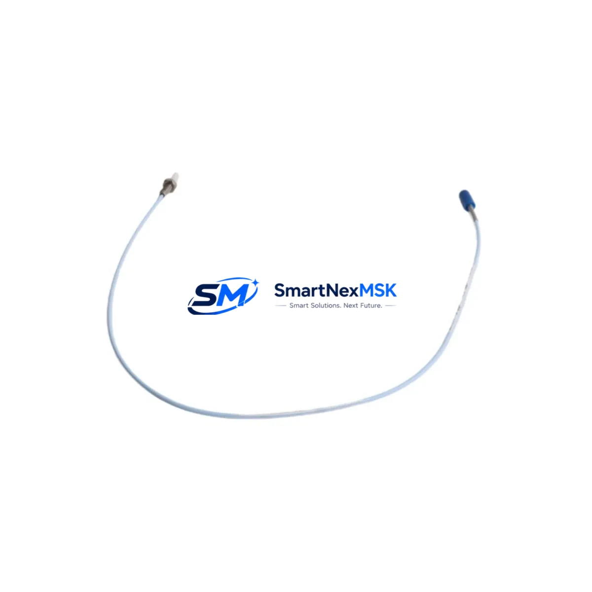
Bently Nevada 330901-22-40-10-01-00 Spare 3300 XL: Precision Spare Part for Industrial Vibration Monitoring Systems
The Bently Nevada 330901-22-40-10-01-00 is an original eddy-current proximity transducer engineered for the 3300 XL Series continuous vibration monitoring platform. Designed for critical rotating machinery — including turbines, compressors, pumps, and motors — this transducer delivers high-resolution shaft displacement and vibration measurements essential for predictive maintenance and machinery protection programs. When a transducer fails or degrades in a live production environment, every minute of unplanned downtime translates directly into lost output and elevated repair costs. Stocking a verified spare of the 330901-22-40-10-01-00 is a fundamental element of any responsible maintenance strategy for facilities running Bently Nevada 3300 XL monitoring systems.
This unit ships fully tested, individually packaged, and covered by a 12-month warranty. Each unit undergoes pre-shipment electrical verification to confirm output sensitivity, gap voltage linearity, and cable integrity — ensuring it is ready for immediate installation upon arrival at your facility.
Spare Maintenance Table
| Parameter | Specification / Detail |
|---|---|
| Part Number / SKU | 330901-22-40-10-01-00 |
| Brand | Bently Nevada |
| Series | 3300 XL Proximity Transducer System |
| Product Type | Eddy-Current Proximity Transducer |
| Probe Length | 22 mm (standard) |
| Cable Length | 40 cm (integral cable) |
| Output Sensitivity | 7.87 V/mm (200 mV/mil) |
| Operating Gap Range | 0.25 mm – 2.54 mm (10–100 mil) |
| Supply Voltage | -24 VDC (nominal) |
| Temperature Range | -35°C to +120°C |
| Target Material | AISI 4140 steel (standard) |
| Connector Type | Integral coaxial cable with BNC/TNC termination |
| Compatibility | Bently Nevada 3300 XL Monitor, 3500 Series (with adapter), TK3 Extension Cable |
| Application | Shaft radial vibration, axial position, differential expansion monitoring |
| Installation Environment | Industrial — turbine halls, compressor stations, pump skids |
| Origin | USA |
| Warranty | 12 Months — covers manufacturing defects and electrical performance |
| Pre-Shipment Test | Gap voltage, sensitivity linearity, insulation resistance verified |
Maintenance Planning for Continuous Operation
Replacing the 330901-22-40-10-01-00 in the field is rarely an isolated task. A thorough maintenance engineer will treat a transducer swap as an opportunity to inspect the entire vibration monitoring loop and adjacent control cabinet components. Begin by verifying the TK3 extension cable (typically 5 m or 9 m) that connects the probe to the proximitor driver — cable shield integrity and connector seating are common sources of signal noise that are often misdiagnosed as transducer failure.
The 3300 XL Proximitor / Oscillator-Demodulator (driver module, e.g., 330180 series) should be inspected for output voltage drift and supply rail stability. If the proximitor is showing erratic gap voltage readings, replacing the transducer alone will not resolve the fault. Simultaneously, check the 3300 XL Monitor rack power supply module — a sagging -24 VDC rail will cause false alarms and measurement offsets across all channels in the rack.
For facilities running multi-channel vibration racks, inspect the 3500/22M Transient Data Interface or equivalent data acquisition module for firmware currency and channel calibration records. If the system feeds a DCS historian or safety instrumented system (SIS), confirm that the 4–20 mA output from the monitor card is within calibrated range before returning the loop to service.
During the same maintenance window, it is good practice to inspect terminal blocks and DIN rail assemblies in the control cabinet for corrosion, loose ferrules, and thermal discoloration — particularly on the signal common and shield drain terminals associated with the transducer loop. Verify that signal isolators or galvanic isolators in the loop (if installed to break ground loops) are functioning correctly, as a failed isolator can introduce noise that mimics transducer degradation.
If the machinery protection system includes relay output modules for alarm and trip functions, test the relay coil resistance and contact continuity while the system is in maintenance mode. Relay contacts that have experienced repeated trip cycling may show elevated contact resistance, leading to delayed or missed trip signals. Additionally, review the Keyphasor transducer (e.g., 330980 series) installed on the same shaft — Keyphasor signal quality directly affects phase and 1X/2X vector calculations across all radial channels.
For older 3300 XL installations approaching end-of-life, consider stocking a complete transducer kit including the probe, extension cable, and proximitor as a matched set. This approach eliminates calibration uncertainty during emergency replacements and is strongly recommended for critical machinery where unplanned downtime carries high operational risk.
Site Replacement Workflow
Step 1 — Isolation and Permit: Obtain a valid work permit and isolate the monitoring channel at the rack. Place the channel in bypass mode to prevent spurious trips during the replacement procedure. Document the current gap voltage reading before disconnecting the existing transducer.
Step 2 — Transducer Removal: Disconnect the TK3 extension cable at the proximitor end. Unthread the existing 330901-22-40-10-01-00 probe from the mounting bracket. Inspect the probe tip for physical damage, contamination, or corrosion that may indicate a broader environmental issue at the measurement point.
Step 3 — Installation of Replacement Unit: Thread the new 330901-22-40-10-01-00 into the mounting bracket. Set the probe gap to the manufacturer-specified nominal gap (typically 1.0–1.5 mm for standard steel targets) using a calibrated feeler gauge or gap-setting tool. Reconnect the extension cable and verify connector seating.
Step 4 — Electrical Verification: With the system powered, measure the gap voltage at the proximitor output. Confirm the reading falls within the linear range (typically -10 VDC to -18 VDC for a correctly gapped probe). Compare against the pre-removal baseline and the channel calibration record.
Step 5 — Functional Test and Return to Service: Remove the channel bypass, confirm alarm and trip setpoints are active, and verify that the DCS or historian is receiving a valid signal. Document the replacement in the equipment maintenance log, including the new unit’s serial number and post-installation gap voltage.
This workflow minimizes downtime, ensures system compatibility is maintained, and provides a complete audit trail for regulatory and reliability review purposes.
Spare Parts Support FAQ
Q1: Is the 330901-22-40-10-01-00 a direct drop-in replacement for older 3300 XL transducers?
Yes. The 330901-22-40-10-01-00 is dimensionally and electrically compatible with the standard 3300 XL proximity transducer system. It uses the same 7.87 V/mm sensitivity and -24 VDC supply as the original specification, making it a direct replacement without recalibration of the proximitor driver in most installations. Always verify the target material and gap setting against your site-specific calibration record before returning the channel to service.
Q2: What is included in the 12-month warranty, and what does it cover?
The 12-month warranty covers manufacturing defects, electrical performance deviations from published specifications, and premature failure under normal operating conditions. Each unit is pre-tested prior to shipment for gap voltage linearity, output sensitivity, and cable insulation resistance. Warranty claims require the original order reference and a description of the failure mode. Physical damage caused by improper installation or mechanical impact is excluded.
Q3: How should this spare part be stored if not immediately installed?
Store the 330901-22-40-10-01-00 in its original packaging in a dry, temperature-controlled environment (0°C to 40°C, relative humidity below 85% non-condensing). Avoid storing near strong magnetic fields or sources of mechanical vibration. Inspect the probe tip and cable connector for contamination before installation if the unit has been in storage for more than 12 months. Long-term storage beyond 3 years should include a pre-installation electrical verification test.
Q4: Can you supply matched sets of transducer, extension cable, and proximitor for emergency stock?
Yes. We recommend stocking matched sets — probe (330901-22-40-10-01-00), TK3 extension cable (5 m or 9 m), and 3300 XL proximitor module — as a complete channel replacement kit. This eliminates compatibility uncertainty during emergency shutdowns and reduces mean time to repair (MTTR). Contact our team to configure a kit matched to your specific rack layout and cable run lengths.
© 2026 SMARTNEXMSK. All rights reserved.
Original Source: https://smartnexmsk.com
Contact: [email protected] | +86 18259474341



