
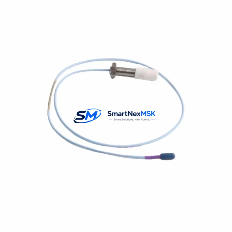
Bently Nevada 330905-00-10-10-02-00 Maintenance-Ready Spare for 3300 XL Automation
The Bently Nevada 330905-00-10-10-02-00 is an 8mm eddy-current proximity transducer engineered for the 3300 XL Series continuous vibration monitoring platform. As a critical sensing element in rotating machinery protection systems — including steam turbines, gas compressors, centrifugal pumps, and large induction motors — this transducer converts shaft displacement into a precise DC voltage signal that feeds directly into the 3300 XL monitor rack. When this component degrades or fails, the entire vibration channel goes blind, exposing the machine to undetected rotor instability, bearing wear, and catastrophic mechanical failure.
For maintenance engineers managing aging turbomachinery or DCS-integrated protection loops, holding a verified spare of the 330905-00-10-10-02-00 is not optional — it is a fundamental element of any credible predictive maintenance program. Unplanned downtime caused by a failed proximity transducer can cost tens of thousands of dollars per hour in lost production. A pre-tested, shelf-ready replacement eliminates that risk and restores full vibration monitoring capability within a single maintenance window.
Every unit shipped by SMARTNEXMSK undergoes functional verification against Bently Nevada factory specifications before dispatch. Each order includes a 12-month warranty covering manufacturing defects and electrical performance. We maintain long-term inventory of 3300 XL Series components to support both emergency callouts and scheduled annual turnarounds.
Spare Maintenance Table
| Parameter | Specification |
|---|---|
| Part Number | 330905-00-10-10-02-00 |
| Brand | Bently Nevada |
| Series | 3300 XL |
| Type | Proximity Transducer (Eddy-Current) |
| Probe Tip Diameter | 8 mm |
| Nominal Gap Voltage | −10 VDC (at 1.0 mm gap) |
| Scale Factor | 7.87 V/mm (200 mV/mil) |
| Linear Range | 0.25 mm – 2.25 mm (10 – 90 mil) |
| Cable Length | 1.0 m integral cable (330130 extension required) |
| Operating Temperature | −35°C to +120°C |
| Compatibility | 3300 XL Monitor Rack, 3300/16 Monitor, 3300/55 Monitor |
| Mating Extension Cable | 330130 Series (1 m, 5 m, 9 m options) |
| Mating Proximitor | 330180 Proximitor Sensor |
| Installation Torque | Per OEM bracket spec (typically 2–4 Nm) |
| Application Environment | Turbines, compressors, pumps, motors — oil-mist, high-vibration, high-temperature |
| Origin | USA |
| Condition | Original — tested before shipment |
| Warranty | 12 Months from shipment date |
| Lead Time | In stock — ships within 1–3 business days |
Maintenance Planning for Continuous Operation
Replacing the 330905-00-10-10-02-00 transducer in the field is rarely an isolated task. A disciplined maintenance engineer treats this replacement as a trigger for a broader inspection of the entire vibration monitoring loop and the surrounding control cabinet. The following components should be inspected, tested, or replaced concurrently to ensure the channel is fully restored and the machine is protected.
Extension Cable — 330130 Series: The coaxial extension cable connecting the probe to the Proximitor is subject to mechanical fatigue, connector corrosion, and insulation breakdown in high-temperature environments. A degraded cable introduces gap voltage errors that mimic transducer failure. Always inspect or replace the 330130 extension cable when changing the probe — available in 1 m, 5 m, and 9 m lengths to suit different cabinet-to-machine distances.
Proximitor Sensor — 330180: The 330180 Proximitor oscillator-demodulator converts the probe’s eddy-current signal into a DC voltage. If the transducer has failed due to electrical overstress, the Proximitor may have been damaged simultaneously. Verify output voltage at the monitor input terminals before closing the loop. A spare 330180 should be held alongside every 330905-00-10-10-02-00 in any serious spare parts kit.
3300 XL Monitor Card: The monitor card processes the gap voltage and generates alarm and danger relay outputs. During a planned outage, verify that the monitor’s OK relay, alarm setpoints, and danger setpoints are correctly configured and that the card firmware is current. A faulty 3300 XL monitor card can mask a healthy transducer signal and generate false channel-not-OK conditions.
Rack Power Supply Module: The 3300 XL rack relies on a dedicated −24 VDC power supply module to bias the Proximitor circuit. Voltage ripple or supply degradation directly affects transducer linearity and gap voltage accuracy. Inspect the rack power supply module and verify output voltage under load during the maintenance window — a marginal supply is a common root cause of intermittent vibration channel faults.
I/O Terminal Blocks and Field Wiring: Loose or corroded terminal connections on the monitor rack’s I/O terminal blocks are a frequent source of intermittent channel faults. Clean and re-torque all field wiring terminations when the transducer is replaced. Pay particular attention to the shield drain wire continuity — an open shield on the extension cable will introduce electrical noise that appears as high vibration at the monitor.
Danger Relay Output Module: The danger relay output from the 3300 XL monitor feeds the machine’s trip logic — typically a safety relay or SIS input card. Verify relay contact resistance and trip function with a loop test after the transducer replacement is complete. A welded or high-resistance relay contact can prevent a legitimate machine trip from executing.
Modbus / Ethernet Communication Gateway: If the 3300 XL rack communicates vibration data to a DCS or SCADA system via a Modbus or Ethernet gateway module, confirm that the channel data is correctly mapped and that the gateway is reporting valid values after the replacement. A channel that reads correctly at the local monitor but shows stale data at the DCS indicates a communication configuration issue requiring gateway reset or re-mapping.
Signal Isolator and Fuse Protection: Check the rack’s internal fuse holders for the affected channel. A blown fuse on the Proximitor supply line will prevent the transducer from operating even if the probe itself is new. Where signal isolators are installed between the 3300 XL output and the DCS analog input card, verify isolator output range and zero/span calibration after the channel is restored.
Probe Bracket and Mounting Hardware: Probe brackets in high-vibration environments are subject to fatigue cracking and elongated mounting holes. If the bracket shows any signs of cracking or corrosion, replace it before installing the new transducer. An unstable bracket introduces mechanical noise into the gap signal and generates nuisance alarms that can mask real machine faults.
Maintaining a consolidated spare kit — including the 330905-00-10-10-02-00 probe, a 330130 extension cable, a 330180 Proximitor, a set of terminal block connectors, and the correct-rated fuses — allows a maintenance team to restore a failed vibration channel in under two hours, even during a night-shift emergency callout.
Site Replacement Workflow
Step 1 — Isolation and Permit: Obtain a work permit and isolate the vibration monitoring channel at the 3300 XL monitor rack. Place the monitor in bypass mode to prevent a spurious machine trip during the replacement. Document the existing gap voltage reading before disconnecting the probe — this baseline confirms whether the fault was in the probe, cable, or Proximitor.
Step 2 — Probe Removal: Disconnect the 330130 extension cable at the probe connector. Using the correct spanner, unscrew the 330905-00-10-10-02-00 probe from its bracket. Note the number of turns required to achieve the nominal gap — this serves as a reference for the new probe installation and speeds up gap-setting on the replacement unit.
Step 3 — New Probe Installation: Thread the replacement 330905-00-10-10-02-00 into the bracket. Set the gap to achieve a nominal output of −10 VDC ± 0.5 VDC as measured at the 330180 Proximitor output terminals. Lock the probe in position with the locknut and reconnect the extension cable, ensuring the connector is fully seated and the locking collar is tight.
Step 4 — Signal Verification: With the Proximitor powered, measure the gap voltage at the monitor input. Confirm the reading is within the linear range (−7 VDC to −18 VDC). Verify that the monitor’s OK indicator is illuminated and that no alarms are active. Cross-check the vibration reading at the DCS or SCADA display to confirm end-to-end channel integrity.
Step 5 — Functional Test and Release: Remove the bypass, confirm that the vibration channel is reading correctly at both the local 3300 XL monitor and the DCS display, and close out the work permit. Update the maintenance record with the replacement date, new probe serial number, and measured gap voltage. This workflow is compatible with both hot-standby and cold-standby replacement scenarios and applies equally to legacy 3300 Series installations being upgraded to 3300 XL hardware.
Spare Parts Support FAQ
Q1: Is the 330905-00-10-10-02-00 compatible with older 3300 Series monitors, or only the 3300 XL?
The 330905-00-10-10-02-00 is designed for the 3300 XL platform but is electrically compatible with earlier 3300 Series monitors that accept 8 mm probes with a 200 mV/mil scale factor. Always verify the monitor’s input specification before installation. If you are migrating from a legacy 3300 monitor to the 3300 XL, the probe and 330130 extension cable can typically be reused without modification.
Q2: What is your inventory policy for long-term supply of 3300 XL spare parts?
SMARTNEXMSK maintains a dedicated buffer stock of high-demand 3300 XL components, including the 330905-00-10-10-02-00, to support both emergency orders and annual turnaround planning. We recommend that facilities with multiple 3300 XL channels hold a minimum of one spare probe and one spare 330180 Proximitor per four monitored channels. Contact our team to discuss consignment or blanket order arrangements for long-term supply security.
Q3: How is each unit tested before shipment?
Every 330905-00-10-10-02-00 unit is bench-tested using a calibrated 330180 Proximitor and a reference target to verify gap voltage linearity across the full measurement range. The scale factor, linear range endpoints, and OK output are confirmed against Bently Nevada factory tolerances. A test report is available upon request. All units are shipped in anti-static packaging with a calibration reference card.
Q4: What does the 12-month warranty cover, and how is a warranty claim processed?
The 12-month warranty covers manufacturing defects, electrical performance deviations from published specifications, and premature failure under normal operating conditions. It does not cover damage caused by incorrect installation, mechanical impact, or operation outside the specified temperature and gap range. To initiate a warranty claim, contact [email protected] with the order number, installation date, and a description of the fault. Replacement units are dispatched within 3 business days of claim approval.
© 2026 SMARTNEXMSK. All rights reserved.
Original Source: https://smartnexmsk.com
Contact: [email protected] | +86 18259474341



