
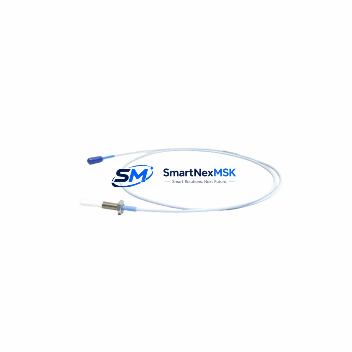
Bently Nevada 330908-00-16-10-01-05 Retrofit-Ready Extension Cable for 3300 XL Control Systems
The Bently Nevada 330908-00-16-10-01-05 is a 16-foot (approximately 5-meter) proximity probe extension cable engineered for seamless integration into Bently Nevada 3300 XL vibration monitoring systems. As legacy machinery protection platforms age and OEM spare parts become increasingly difficult to source, this cable serves as a verified drop-in replacement for discontinued or end-of-life extension cables within the 3300 series ecosystem. Whether you are executing a planned turnaround, responding to an unplanned trip, or modernizing an aging control cabinet, the 330908-00-16-10-01-05 delivers the signal integrity and mechanical compatibility required to restore full system functionality with minimal downtime.
This extension cable is designed to bridge the 330900 series proximity probes to the 3300/16 proximitor/seismic monitor and compatible rack-mounted signal conditioning modules. The cable maintains the precise impedance and capacitance characteristics required by the 3300 XL signal chain, ensuring that eddy-current probe gap voltage, vibration amplitude, and phase reference signals are transmitted without degradation. Engineers replacing worn or damaged cables during a scheduled outage can install this unit without recalibrating the proximitor or adjusting monitor setpoints, provided the probe-to-target gap is verified during reinstallation.
Upgrade Compatibility Table
| Parameter | Detail |
|---|---|
| SKU / Part Number | 330908-00-16-10-01-05 |
| Brand / Series | Bently Nevada 3300 XL |
| Cable Length | 16 ft (approx. 5 m) |
| Compatible Probes | 330900 series proximity probes (8 mm) |
| Compatible Monitors | 3300/16 Proximitor/Seismic Monitor; 3300/20 Radial Vibration Monitor |
| Connector Interface | Standard BNC / coaxial termination per 3300 XL specification |
| Installation Requirement | No recalibration required if probe gap is within specification |
| Communication Compatibility | Analog 4–20 mA / voltage output; compatible with System 1 software |
| Replacement Recommendation | Direct drop-in for discontinued 330908 variants; verify jacket condition and connector seating |
| Commissioning Focus | Gap voltage verification, OK relay status, alarm setpoint confirmation |
| Warranty | 12-Month Warranty |
Retrofit Planning for Existing Automation Systems
Successful retrofit of the 330908-00-16-10-01-05 into an operating plant begins well before the cable arrives on site. Maintenance engineers should first audit the existing wiring layout within the machinery protection cabinet, confirming that the 3300/16 monitor card slot assignment and channel address match the original configuration. In multi-channel racks housing both radial vibration and axial position channels, it is common to find the 3300/20 Radial Vibration Monitor and 3300/55 Dual Voting Logic modules occupying adjacent slots; any cable routing change must account for the physical clearance between these modules and the backplane connectors of the 3300 XL rack.
Before disconnecting the old cable, technicians should document the existing gap voltage reading displayed on the 3300/16 monitor front panel or within Bently Nevada System 1 condition monitoring software. This baseline reading — typically between −10 VDC and −18 VDC for an 8 mm probe at nominal gap — serves as the acceptance criterion after the new 330908-00-16-10-01-05 is installed. If the plant uses a TK-3 proximitor or an older 3300 XL proximitor/seismic unit mounted remotely from the rack, confirm that the total cable loop length (probe cable plus extension cable) does not exceed the system’s specified maximum, as excess capacitance will shift the linear range of the eddy-current measurement.
For facilities migrating from older 3300 series hardware to the 3500 series machinery protection platform, the 330908-00-16-10-01-05 can serve as an interim solution during phased migration. In this scenario, the existing 330900 probes and extension cables remain in service while the 3500/42M Proximitor/Seismic Monitor and associated 3500 rack are installed in parallel. Once the new rack is commissioned and alarm setpoints are verified in System 1 software, the cutover can be executed channel by channel, dramatically reducing the risk of a full-system outage. During this transition, the 3500/22M Transient Data Interface and 3500/92 Communication Gateway modules are typically added to the new rack to preserve Modbus or OPC-DA connectivity to the plant DCS.
Power supply capacity within the existing control cabinet must also be reviewed. The 3300 XL rack draws power from a dedicated 3300/10 Power Supply module; if additional I/O cards or communication modules are being added as part of the upgrade, verify that the power supply’s output current rating is not exceeded. In cabinets where the original 3300/10 is already at capacity, a supplemental power rail or a replacement with a higher-rated unit may be required before the retrofit can proceed safely.
Downtime Control During System Migration
Minimizing unplanned downtime during a cable replacement or system migration requires a structured pre-outage preparation protocol. Before the maintenance window opens, the replacement 330908-00-16-10-01-05 cable should be bench-tested for continuity and insulation resistance, and the connector terminations should be inspected under magnification to confirm that the center conductor and shield are properly seated. A pre-tested spare eliminates the risk of discovering a defective cable after the machine is already offline.
During the outage, the original program logic stored in the 3300/16 monitor — including danger and alert setpoints, time delays, and voting logic configurations — should be exported from System 1 or recorded manually before any hardware is disturbed. This ensures that if a monitor card must be replaced alongside the cable, the setpoints can be restored exactly as commissioned, without requiring a full functional safety review. For plants operating under IEC 61511 or API 670 requirements, this documentation step is mandatory and must be completed before the permit-to-work is issued.
After the new cable is installed and the machine is returned to service, the gap voltage, direct vibration, and 1X/2X vector readings should be trended for the first 24–48 hours of operation to confirm that the signal chain is performing within historical norms. Any deviation greater than 10% from the pre-outage baseline warrants investigation before the machinery protection system is returned to automatic trip mode. This structured commissioning approach, combined with in-stock availability of the 330908-00-16-10-01-05 and a 12-month warranty, ensures that your retrofit project stays on schedule and within budget.
Retrofit Support FAQ
Q1: Is the 330908-00-16-10-01-05 a direct replacement for all 330908 variants?
The 330908-00-16-10-01-05 is a 16-foot extension cable and is a direct replacement for other 330908 variants of the same length. If your existing installation uses a different length variant (e.g., 330908-00-25 for 25 ft), you must select the matching length to preserve the system’s calibrated linear range. Mixing cable lengths without recalibrating the proximitor will shift the gap voltage baseline and may trigger false alarms or missed trips.
Q2: Do I need to recalibrate the 3300/16 monitor after replacing the extension cable?
In most cases, no recalibration is required if the replacement cable is the same length and specification as the original, and the probe-to-target gap is restored to the original commissioned value. However, if the probe was also disturbed during the cable replacement, the gap voltage must be re-verified and the OK relay status confirmed before returning the channel to service. Always cross-reference the as-built gap voltage record from System 1 or the original commissioning report.
Q3: What connector and wiring checks should be performed before energizing the system?
Before energizing, verify that the BNC connector at the proximitor input is fully seated and the locking collar is finger-tight. Inspect the probe end connector for corrosion or mechanical damage, particularly in high-temperature or high-humidity environments. Confirm that the cable jacket is free of cuts or abrasion that could compromise the shield continuity. A simple insulation resistance test at 500 VDC between the center conductor and shield, with a minimum acceptable reading of 100 MΩ, will confirm cable integrity before the system is powered.
Q4: What does the 12-month warranty cover, and how is it supported?
The 12-month warranty covers manufacturing defects in materials and workmanship under normal operating conditions. Each unit undergoes outgoing quality inspection and functional testing prior to shipment. In the event of a warranty claim, contact our technical support team with the purchase order number, installation date, and a description of the observed fault. Replacement units are dispatched from stock to minimize your system downtime, and our engineers can provide remote commissioning guidance to support your on-site team during reinstallation.
© 2026 SMARTNEXMSK. All rights reserved.
Original Source: https://smartnexmsk.com
Contact: [email protected] | +86 18259474341



