
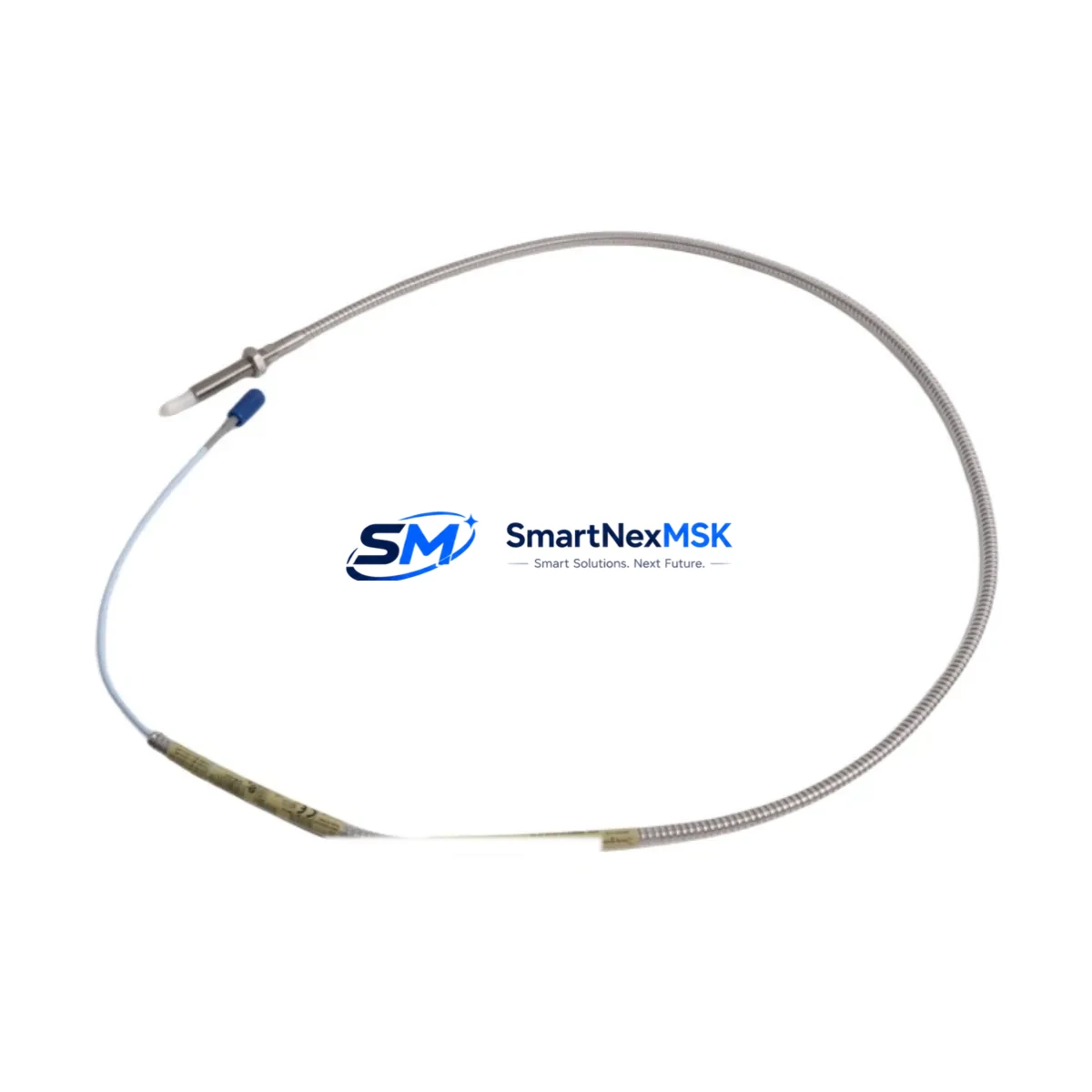
Bently Nevada 330909-00-25-10-02-00 Spare for 3300 Series Automation: Precision Replacement for Minimized Downtime
The Bently Nevada 330909-00-25-10-02-00 is an eddy-current proximity transducer engineered for continuous vibration and position monitoring in rotating machinery applications. As a maintenance-ready spare, this unit is sourced, inspected, and dispatched to support rapid field replacement in turbines, compressors, pumps, and other critical rotating assets where unplanned downtime carries significant operational and financial risk. Whether you are executing a planned outage, responding to a vibration alarm, or building a strategic spare parts inventory, the 330909-00-25-10-02-00 delivers the dimensional and electrical compatibility required for direct substitution within the Bently Nevada 3300 Series monitoring architecture.
Maintenance engineers working on legacy and current-generation machinery protection systems recognize the 3300 Series as one of the most widely deployed eddy-current transducer platforms in industrial service. The 330909-00-25-10-02-00 integrates directly with 3300 Series signal conditioning modules, eliminating the need for recalibration of the monitoring rack when a like-for-like replacement is performed. This compatibility is critical in facilities where vibration monitoring systems are governed by API 670 or equivalent machinery protection standards, and where any deviation from the qualified transducer specification must be formally documented and approved.
For procurement engineers, maintaining a buffer stock of the 330909-00-25-10-02-00 is a straightforward risk mitigation measure. Lead times on OEM-sourced transducers can extend to several weeks during peak demand periods, and a single unplanned compressor or turbine trip caused by a failed proximity transducer can cost far more than the value of an entire spare parts inventory. Stocking one or two units per critical machine train is a widely accepted practice in reliability-centered maintenance programs.
Spare Maintenance Table
| Parameter | Specification / Detail |
|---|---|
| Part Number | 330909-00-25-10-02-00 |
| Brand | Bently Nevada |
| Series | 3300 Series |
| Type | Eddy-Current Proximity Transducer |
| Cable Length | 25 ft (7.62 m) — encoded in SKU segment “-25” |
| Tip Diameter | 10 mm — encoded in SKU segment “-10” |
| Output | -200 mV/mil (standard 3300 Series output) |
| Operating Temperature | -35°C to +121°C (sensor tip) |
| Supply Voltage | -24 VDC (via Proximitor / signal conditioner) |
| Target Material Compatibility | AISI 4140 steel (standard); verify for non-ferrous targets |
| Connector Type | MIL-C-5015 style (verify with mating Proximitor) |
| Mounting Thread | 3/8-24 UNF (standard 3300 Series) |
| Application | Radial vibration, axial position, differential expansion monitoring |
| Compatible Monitors | 3300/16, 3300/20, 3300/25, 3300/55 series racks |
| Origin | USA |
| Condition | Original spare — tested before dispatch |
| Warranty | 12 Months |
| Lead Time | In-stock: 3–7 business days; subject to availability |
Maintenance Planning for Continuous Operation
A proximity transducer replacement should never be treated as an isolated task. When a 330909-00-25-10-02-00 is removed from service — whether due to cable damage, tip contamination, sensitivity drift, or physical impact — the surrounding system components deserve equal scrutiny before the machine is returned to operation.
Begin with the Proximitor / signal conditioner (typically a 3300 XL 8mm or 3300 XL 11mm Proximitor, depending on the transducer tip size). The Proximitor converts the raw oscillator signal into a DC voltage proportional to gap distance; a degraded Proximitor can produce erratic output even with a new transducer installed. Verify the Proximitor output voltage at the nominal gap before closing the machine.
Inspect the extension cable connecting the transducer to the Proximitor. The 3300 Series system is calibrated as a matched set — transducer, extension cable, and Proximitor — and substituting a cable of incorrect length or impedance will shift the system sensitivity. Confirm the extension cable part number matches the calibrated system specification.
Check the -24 VDC power supply feeding the Proximitor. Voltage sag or ripple on the supply rail can introduce noise into the vibration signal and trigger false alarms. A dedicated power supply module within the 3300 Series rack should be load-tested if the machine has been in service for more than three years without a rack inspection.
Review the 3300 Series monitor card (e.g., 3300/16 Dual Vibration Monitor or 3300/25 Keyphasor Module) for alarm setpoint integrity and relay output status. Relay output contacts on these cards are subject to contact wear over time; a relay output module showing intermittent trip behavior should be replaced during the same outage window.
For machines equipped with a Keyphasor transducer (also a 3300 Series eddy-current device), verify that the once-per-revolution reference signal is clean and correctly phased. A degraded Keyphasor will corrupt phase angle readings across all vibration channels on the rack.
Inspect terminal blocks and field wiring at the junction box. Loose terminations on the transducer signal pair introduce common-mode noise that is indistinguishable from real vibration at the monitor. Torque all terminals to specification and verify shield grounding continuity.
If the machine is part of a DCS or safety instrumented system (SIS) integration, confirm that the 4–20 mA output from the vibration monitor is correctly received at the DCS I/O card or signal isolator. A failed signal isolator between the vibration rack and the DCS can mask a genuine vibration alarm at the control room level — a dangerous condition in high-consequence rotating equipment applications.
Finally, document the replacement in the CMMS (Computerized Maintenance Management System) with the new transducer serial number, installation gap voltage, and post-installation vibration baseline. This record supports future condition trending and spare parts lifecycle planning.
Site Replacement Workflow
Step 1 — Isolation and lockout: Follow site LOTO procedures. Confirm the machine is at rest and the monitoring rack is in bypass mode to prevent spurious trips during transducer removal.
Step 2 — Gap measurement before removal: Record the existing gap voltage (typically -10 VDC ± 1 VDC at nominal gap for a 3300 Series 10 mm transducer). This baseline confirms whether the old transducer was operating within specification or had already drifted.
Step 3 — Remove the old transducer: Unthread the transducer from the bracket. Inspect the bracket bore for wear, corrosion, or thread damage. A damaged bracket will prevent correct gap setting on the new unit.
Step 4 — Install the 330909-00-25-10-02-00: Thread the new transducer into the bracket. Set the gap to the system-specified value (typically 50 mil / 1.27 mm for a 10 mm tip, yielding approximately -10 VDC output). Use a calibrated gap-setting tool or feeler gauge. Lock the transducer in position with the locknut.
Step 5 — Verify output voltage: With the Proximitor powered, measure the DC output voltage at the monitor terminal. Confirm it falls within the linear range specified on the system calibration sheet. Adjust gap if necessary.
Step 6 — Return to service: Remove bypass, confirm alarm setpoints are active, and observe the vibration trend for the first 30 minutes of machine operation. Document the post-installation baseline in the CMMS.
This workflow applies equally to radial vibration, axial position, and differential expansion transducer positions. For machines with redundant transducer pairs (XY configuration), replace both transducers during the same outage to maintain matched system sensitivity.
Spare Parts Support FAQ
Q1: Is the 330909-00-25-10-02-00 a direct drop-in replacement for other 3300 Series proximity transducers?
The 330909-00-25-10-02-00 is compatible with 3300 Series monitoring racks when the cable length (25 ft), tip diameter (10 mm), and connector configuration match the installed system specification. The 3300 Series is a matched-system design — always verify that the replacement transducer, extension cable, and Proximitor are calibrated as a set. Substituting only the transducer without verifying the extension cable and Proximitor part numbers may result in sensitivity error.
Q2: What testing is performed before dispatch?
Each unit undergoes functional verification including output voltage check at nominal gap, cable continuity test, and visual inspection of the tip, connector, and cable jacket. Units that do not meet specification are quarantined. A test report is available upon request for critical applications.
Q3: How should I manage spare parts inventory for 3300 Series transducers?
For critical rotating equipment (turbines, compressors, large pumps), a minimum of one spare transducer per machine train is recommended. For facilities with multiple identical machines, a pooled inventory of two to three units per transducer model is typically sufficient. Review spare parts consumption annually and replenish before stock reaches zero — OEM lead times can be unpredictable, and a single unplanned trip event can deplete your entire buffer.
Q4: What is covered under the 12-month warranty?
The 12-month warranty covers manufacturing defects, premature electrical failure under normal operating conditions, and connector or cable integrity issues attributable to the unit as supplied. It does not cover damage resulting from incorrect installation, gap setting outside the specified range, exposure to fluids or environments beyond the rated operating conditions, or physical impact. Warranty claims are processed via [email protected] with photographic evidence and a brief failure description.
© 2026 SMARTNEXMSK. All rights reserved.
Original Source: https://smartnexmsk.com
Contact: [email protected] | +86 18259474341



