
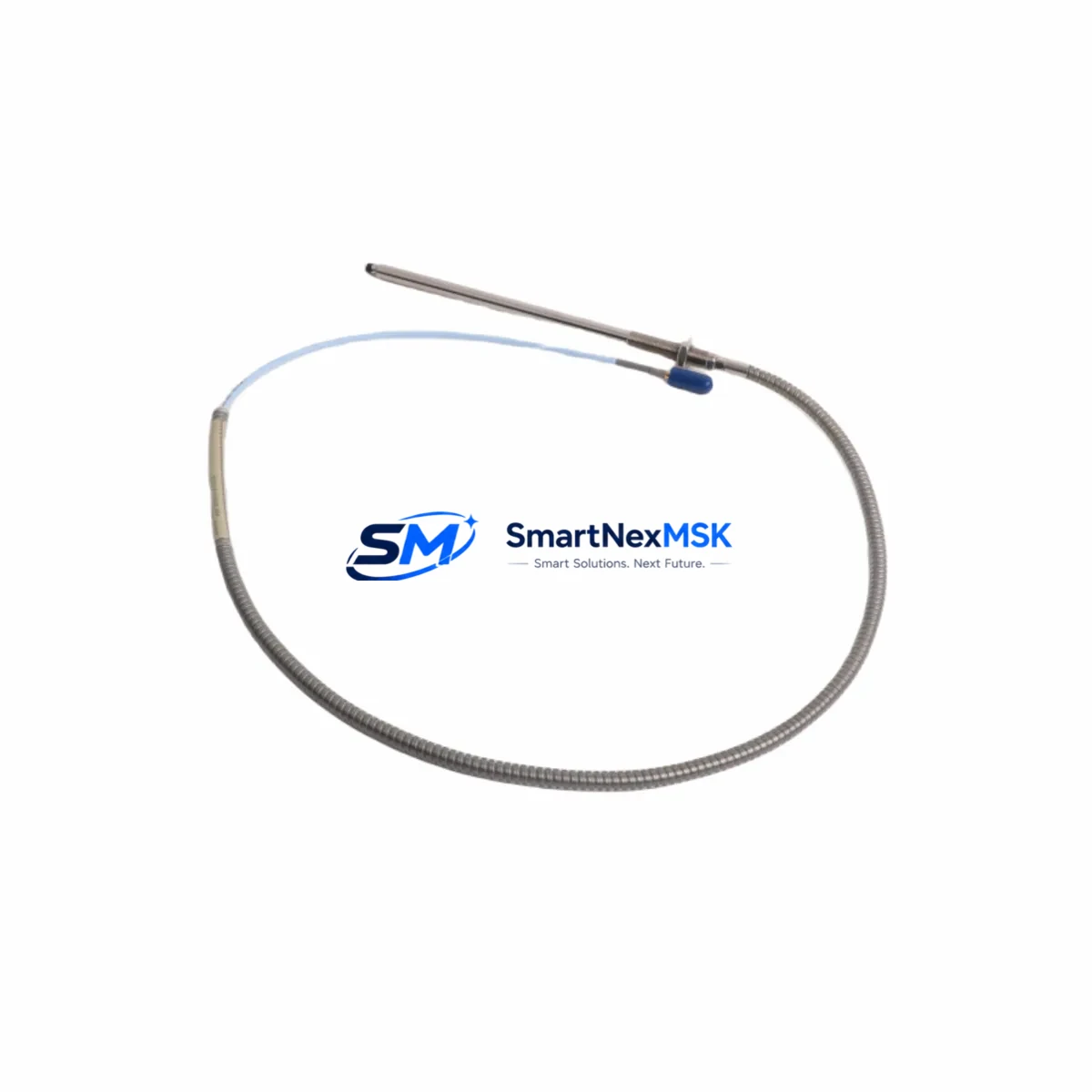
Bently Nevada 330910-014-19-10-02-00 Retrofit-Ready Proximity Probe for 3300 XL Control Systems
The Bently Nevada 330910-014-19-10-02-00 is a high-precision eddy-current proximity probe engineered for seamless integration into Bently Nevada 3300 XL Series vibration monitoring systems. As legacy 3300 XL installations approach end-of-service milestones, this probe serves as the preferred retrofit-ready replacement for engineers managing rotating machinery protection, shaft displacement monitoring, and critical turbine or compressor control loops. Whether you are executing a planned upgrade, recovering from an unplanned failure, or consolidating spare-parts inventory, the 330910-014-19-10-02-00 delivers verified dimensional, electrical, and signal compatibility with existing field wiring and rack infrastructure.
This probe is designed to replace discontinued or aging proximity transducers in 3300 XL monitor racks without requiring changes to the extension cable, driver, or signal conditioning chain. Engineers can retain the existing Bently Nevada 330130 extension cable and 330180 proximitor/driver assemblies already installed in the field, dramatically reducing retrofit scope and downtime exposure. The probe tip diameter, thread specification, and case length conform to the 3300 XL mechanical envelope, allowing direct installation into existing probe holders and bracket assemblies on turbine bearing housings, compressor pedestals, and gearbox end-plates.
Before committing to installation, retrofit planners should verify the following parameters against the existing system documentation: power supply voltage (typically –24 VDC from the monitor rack), gap voltage at the target operating clearance, scale factor (200 mV/mil or 7.87 V/mm depending on system configuration), and OK limit thresholds programmed in the 3300 XL monitor card. Terminal block wiring at the junction box should be confirmed against the original loop drawing, paying particular attention to shield grounding practice and cable routing to avoid EMI coupling from adjacent power conductors.
Upgrade Compatibility Table
| Parameter | 330910-014-19-10-02-00 Specification | Retrofit Note |
|---|---|---|
| Target System | Bently Nevada 3300 XL Series | Direct replacement; no rack modification required |
| Probe Length | 19 mm (short-range) | Confirm bracket standoff matches existing probe holder |
| Cable Connector | 10-32 UNF coaxial | Compatible with 330130 extension cable — no re-termination |
| Driver Compatibility | 330180 Proximitor | Retain existing driver; verify gap voltage after installation |
| Supply Voltage | –24 VDC nominal | Confirm rack power module output before energising |
| Scale Factor | 200 mV/mil | Match to monitor card configuration; recalibrate if changed |
| Communication Protocol | Analogue (4–20 mA / voltage) | No protocol migration required for 3300 XL monitors |
| Installation Interface | M10 × 1.0 thread | Verify probe holder thread before installation |
| Warranty | 12 Months | Covers manufacturing defects; includes pre-shipment functional test |
Retrofit Planning for Existing Automation Systems
A successful 3300 XL retrofit begins well before the maintenance window opens. Start by auditing the full transducer chain: the 330910-014-19-10-02-00 probe, the paired 330130 extension cable, and the 330180 proximitor driver form a matched system. Replacing only the probe while retaining a degraded extension cable or a driver with drifted output impedance will produce erroneous gap readings and may trigger nuisance trips on the 3300/16-channel monitor card. Where the extension cable shows signs of jacket cracking, connector corrosion, or insulation resistance below specification, plan to replace the cable assembly concurrently.
For facilities running mixed Bently Nevada generations — for example, sites that have already migrated some loops to the 3500 Series rack while retaining legacy 3300 XL monitors on non-critical machinery — the 330910-014-19-10-02-00 maintains backward compatibility with the 3300 XL infrastructure, avoiding the need to upgrade the monitor rack, I/O termination modules, or the Keyphasor module used for phase reference. This is particularly valuable in brownfield plants where capital budgets favour incremental upgrades over full platform migrations.
When the retrofit scope does extend to the monitor rack, engineers should account for the 3300/20-20 power supply module capacity before adding channels. Each active transducer loop draws current from the rack power bus; adding replacement probes to previously unused channels requires confirming that the power supply module can sustain the additional load without voltage droop that would affect OK status thresholds. Similarly, if the upgrade path includes migrating HMI trend displays from a legacy System 1 Condition Monitoring workstation to a modern platform, verify that the analogue signal scaling and tag naming conventions are preserved to avoid misinterpretation of historical vibration data.
For sites integrating proximity probe data into a DCS or safety system via the 3300/55 relay module or a 3300/25 buffered output module, confirm that the output signal levels and relay trip setpoints remain valid after probe replacement. Any change in gap voltage at the operating clearance — even within the probe’s specification — can shift the buffered output voltage enough to require setpoint review on the receiving controller or safety instrumented system.
Downtime Control During System Migration
Minimising unplanned downtime during a proximity probe replacement requires a structured hot-swap protocol. Where the process permits, place the affected monitor channel in bypass mode using the 3300 XL monitor’s front-panel or software bypass function before breaking the transducer connection. This prevents a spurious trip signal from propagating to the turbine trip relay or DCS interlock during the probe exchange. Document the bypass activation time in the maintenance log and set a hard time limit for the work scope to ensure the bypass is not left active beyond the approved window.
After installing the 330910-014-19-10-02-00 and reconnecting the extension cable, perform a static gap check using a calibrated DC voltmeter at the proximitor output before releasing the bypass. The gap voltage should fall within the linear range specified for the target material and operating clearance. If the gap voltage is outside the expected window, adjust the probe axial position in the holder before tightening the locknut. Only after confirming a valid gap reading and stable OK status on the monitor card should the bypass be released and the channel returned to protective service.
For critical machinery where continuous monitoring is mandatory, consider deploying a portable SCOUT 100 or SCOUT 140 data collector on adjacent measurement points during the replacement window to maintain situational awareness of machine condition. This approach allows the maintenance team to proceed with confidence while the permanent monitoring channel is temporarily out of service.
Retrofit Support FAQ
Q1: Is the 330910-014-19-10-02-00 a direct drop-in replacement for my existing 3300 XL proximity probe?
In most cases, yes. The probe is dimensionally and electrically compatible with the 3300 XL transducer system when used with the 330130 extension cable and 330180 proximitor. Confirm the probe length suffix (19 mm in this SKU) matches your existing bracket standoff distance before ordering.
Q2: Do I need to recalibrate the monitor card after replacing the probe?
A full recalibration is not always required, but a gap voltage verification is mandatory. If the new probe’s output at the operating clearance differs from the previous probe by more than the monitor’s OK band, adjust the probe position or update the OK limit setpoints accordingly. Retain the original calibration records for comparison.
Q3: What wiring changes are needed at the junction box?
No wiring changes are required if the extension cable and connector are in good condition. The 10-32 UNF coaxial connector mates directly to the 330130 extension cable. Inspect the connector contact and cable shield continuity before re-energising the loop.
Q4: What does the 12-month warranty cover, and is pre-shipment testing performed?
Every 330910-014-19-10-02-00 unit undergoes functional testing prior to shipment, including output voltage verification across the linear range. The 12-month warranty covers manufacturing defects in materials and workmanship from the date of shipment. Warranty claims are supported with replacement or repair at no additional cost.
© 2026 SMARTNEXMSK. All rights reserved.
Original Source: https://smartnexmsk.com
Contact: [email protected] | +86 18259474341



