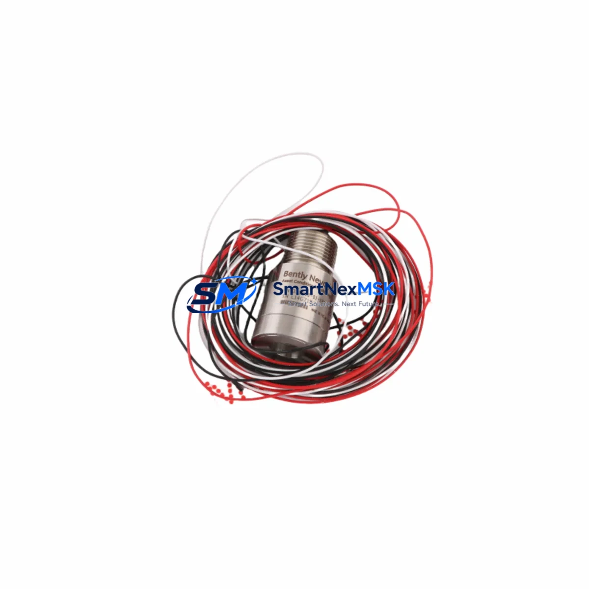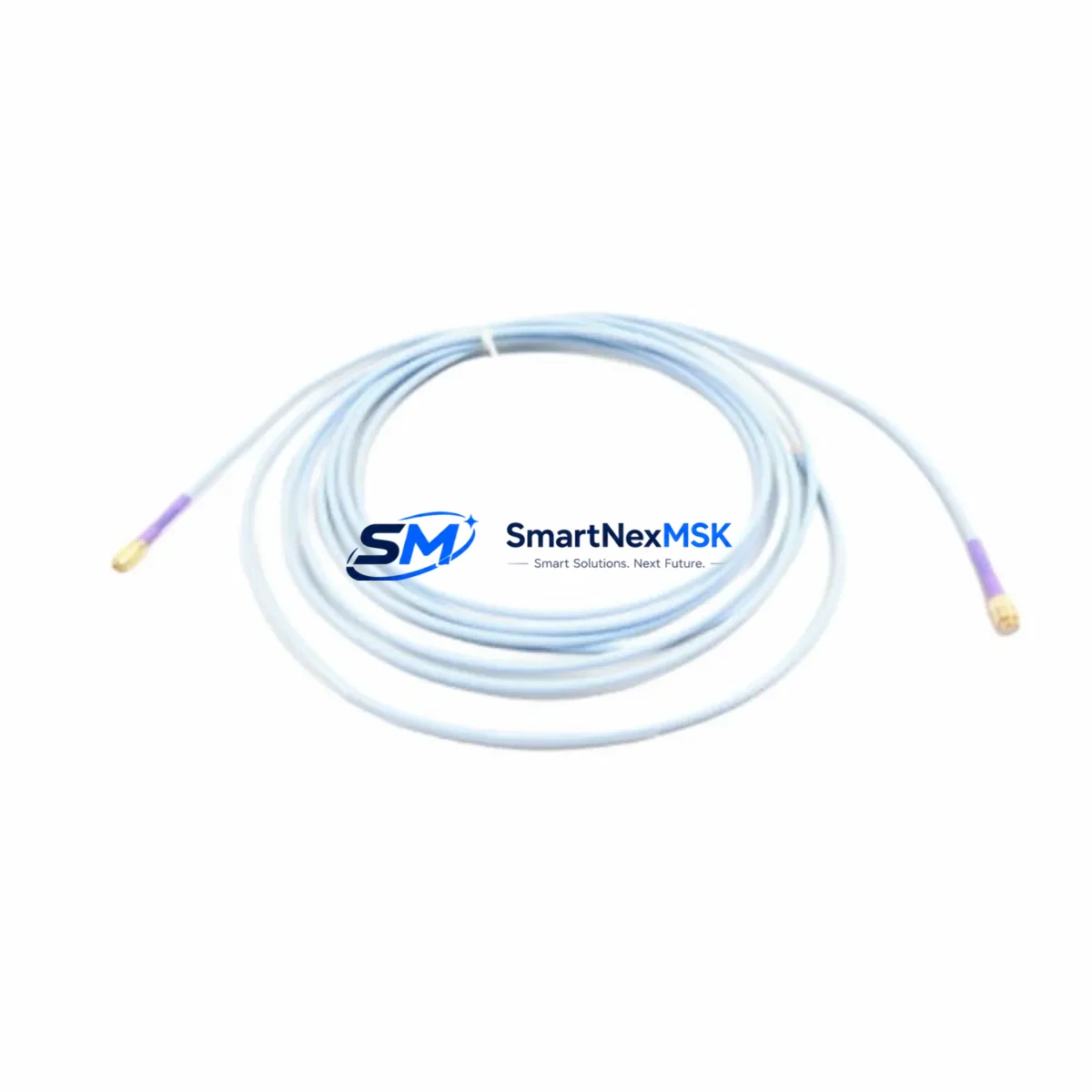
Bently Nevada 330930-040-00-00 Spare for 3300 Automation: Precision Replacement for Vibration Monitoring Continuity
The Bently Nevada 330930-040-00-00 is a 40-foot (approximately 12-metre) Proximitor extension cable engineered for the 3300 Series vibration monitoring system — one of the most widely deployed machinery protection platforms in rotating equipment applications worldwide. For maintenance engineers managing turbines, compressors, pumps, and gearboxes, this cable is a critical link in the signal chain between the proximity probe and the Proximitor sensor. A degraded or failed extension cable can produce erratic vibration readings, false trips, or complete loss of channel data — all of which translate directly into unplanned downtime and production loss.
Sourced as an original Bently Nevada component, the 330930-040-00-00 meets the full electrical and mechanical specification required for 3300 Series installations. It is pre-tested prior to shipment and backed by a 12-month warranty, giving maintenance and procurement teams confidence in both immediate deployment and long-term spare parts planning.
Spare Maintenance Table
| Parameter | Specification |
|---|---|
| Part Number | 330930-040-00-00 |
| Brand | Bently Nevada |
| Series | 3300 Series Vibration Monitoring |
| Type | Proximitor Extension Cable |
| Cable Length | 40 ft (approx. 12 m) |
| Connector Type | Coaxial, compatible with 3300 Series Proximitor sensors |
| Signal Type | Eddy-current proximity probe signal (low-level analogue) |
| Application | Rotating machinery: turbines, compressors, pumps, gearboxes |
| System Compatibility | Bently Nevada 3300 Series, 3500 Series (with verified configuration) |
| Origin | United States |
| Condition | Original, new or reconditioned — tested before shipment |
| Warranty | 12 months from date of shipment |
| Weight | 360 g |
| Maintenance Recommendation | Inspect connectors and cable jacket annually; replace at first sign of insulation damage or signal drift |
Maintenance Planning for Continuous Operation
When a 330930-040-00-00 extension cable is flagged during a routine vibration channel audit or fault isolation exercise, experienced maintenance engineers know that the cable itself is rarely the only component requiring attention. A thorough inspection of the complete signal loop is essential before returning the channel to service.
Begin by verifying the condition of the proximity probe at the measurement point — the Bently Nevada 330103-00-07-10-02-00 or equivalent 3300 Series probe is the upstream source of the eddy-current signal, and connector corrosion or tip damage will produce the same symptoms as a faulty extension cable. Next, inspect the Bently Nevada 3300 XL Proximitor sensor (e.g. 330180-X1-05) mounted in the junction box or field enclosure; a failed Proximitor will not respond correctly even with a new cable installed.
At the rack level, confirm that the 3500/42M Proximitor Monitor or the relevant 3300 Series monitor card is receiving clean power from the 3500/15 Power Supply module. Voltage irregularities on the 24 VDC rail are a common root cause of intermittent channel faults that are incorrectly attributed to cabling. Check the terminal blocks and field wiring connections in the junction box — corroded or loose terminals on the signal and shield conductors will introduce noise that mimics cable degradation.
For installations where the 330930-040-00-00 feeds into a 3500 Series rack rather than a standalone 3300 monitor, also inspect the 3500/20 Rack Interface Module and verify that the system communication bus to the Bently Nevada System 1 Evolution software platform is intact. A communication fault at the rack level can mask genuine vibration data and delay fault diagnosis.
Where the machinery protection system interfaces with a DCS or safety instrumented system, check the 4–20 mA output wiring from the monitor card to the DCS I/O module, and confirm that any signal isolators in the loop — such as those used to prevent ground loops between the field enclosure and the control room — are functioning within specification. Fuse integrity on the field power circuit should also be verified as part of the same inspection round.
Maintaining a minimum stock of one replacement 330930-040-00-00 cable per critical machine train, alongside a spare Proximitor sensor and a set of probe connectors, is a widely adopted strategy in facilities operating continuous processes where unplanned shutdowns carry significant production cost.
Site Replacement Workflow
Step 1 — Isolate and document. Before disconnecting the existing cable, record the current vibration gap voltage and dynamic readings from the monitor. This baseline confirms whether the cable is the fault source or whether the issue originates at the probe or Proximitor.
Step 2 — Disconnect safely. De-energise the Proximitor sensor supply at the field junction box. Disconnect the extension cable at both the probe connector and the Proximitor input. Inspect both connectors for corrosion, bent pins, or damaged threads before installing the replacement.
Step 3 — Install 330930-040-00-00. Route the new cable following the original cable path to avoid mechanical stress or proximity to high-voltage conductors. Secure with appropriate cable ties or conduit fittings. Torque connectors to the manufacturer’s specification — over-tightening damages the coaxial connector body and under-tightening introduces intermittent contact faults.
Step 4 — Re-energise and verify gap voltage. Restore power to the Proximitor and measure the DC gap voltage at the monitor. For a standard 3300 Series installation with an 8 mm probe, the nominal gap voltage should fall within the system’s calibrated range (typically –10 VDC ± 1 V at the set gap). A reading outside this range indicates a probe gap adjustment or a probe/Proximitor fault rather than a cable issue.
Step 5 — Confirm dynamic response. With the machine running, verify that the vibration channel is displaying live dynamic data consistent with historical baseline readings. Log the post-replacement readings in the maintenance management system and update the spare parts inventory record.
This workflow minimises the time the vibration protection channel is offline and ensures the replacement is verified before the machine is returned to full load.
Spare Parts Support FAQ
Q1: Is the 330930-040-00-00 compatible with both 3300 Series and 3500 Series systems?
The 330930-040-00-00 is designed and specified for the Bently Nevada 3300 Series. Compatibility with 3500 Series installations depends on the specific Proximitor sensor and monitor card configuration. We recommend confirming the system drawing and Proximitor model before ordering for a 3500 Series application. Our technical team can assist with compatibility verification prior to shipment.
Q2: What pre-shipment testing is performed on this cable?
Each 330930-040-00-00 unit undergoes continuity, insulation resistance, and connector integrity checks before dispatch. Units that do not meet the original Bently Nevada electrical specification are not shipped. A test record is available upon request for critical applications.
Q3: What does the 12-month warranty cover?
The 12-month warranty covers manufacturing defects and electrical performance failures under normal operating conditions. It does not cover damage resulting from incorrect installation, mechanical abuse, or operation outside the specified environmental range. Warranty claims are processed promptly with replacement or refund options.
Q4: Can you support long-term or blanket orders for this part?
Yes. For facilities managing multiple machine trains or operating in regions where lead times for Bently Nevada spares are extended, we support scheduled delivery agreements and reserved stock arrangements. Contact our team to discuss volume pricing and supply continuity planning for the 330930-040-00-00 and related 3300 Series components.
© 2026 SMARTNEXMSK. All rights reserved.
Original Source: https://smartnexmsk.com
Contact: [email protected] | +86 18259474341