
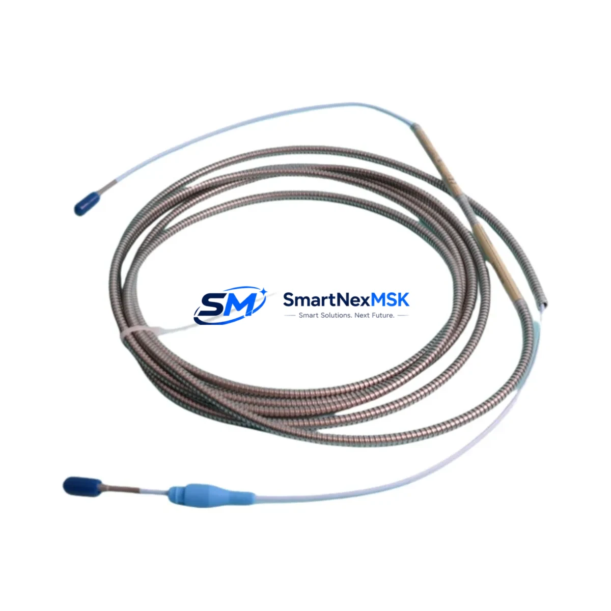
Bently Nevada 330930-040-01-05 3300 Series Spare: Precision Extension Cable for Vibration Monitoring Systems
The Bently Nevada 330930-040-01-05 is a 40-foot (12.2 m) proximity transducer extension cable engineered for the 3300 Series vibration monitoring system — one of the most widely deployed machinery protection platforms in rotating equipment facilities worldwide. Whether you are managing a planned turnaround, responding to an unplanned trip, or building a strategic spare parts inventory for a critical train, this original extension cable ensures signal integrity between the 3300 XL 8 mm proximity transducer and its paired Proximitor® sensor without introducing measurement error or calibration drift.
For maintenance engineers and reliability teams, the extension cable is a frequently overlooked but operationally critical component. Cable degradation — caused by mechanical abrasion, chemical exposure, thermal cycling, or connector corrosion — is a leading cause of false vibration alarms and nuisance trips. Stocking a verified original 330930-040-01-05 eliminates the risk of substituting non-OEM cables that may alter the system’s electrical characteristics and invalidate the calibrated gap voltage range.
Spare Maintenance Table
| Parameter | Specification |
|---|---|
| Part Number | 330930-040-01-05 |
| Brand | Bently Nevada |
| Series | 3300 XL / 3300 Series |
| Type | Proximity Transducer Extension Cable |
| Cable Length | 40 ft (12.2 m) |
| Compatible Transducer | 3300 XL 8 mm Proximity Transducer (e.g. 330780, 330730 series) |
| Compatible Proximitor | 3300 XL Proximitor® Sensor (e.g. 330180, 330185 series) |
| Connector Type | MIL-C-5015 style, gold-plated contacts |
| Operating Temperature | -40°C to +121°C |
| Application Environment | Rotating machinery, turbines, compressors, pumps, gearboxes |
| Installation | Direct replacement; no recalibration required when using OEM cable |
| Condition | Original spare, factory-tested |
| Warranty | 12 Months |
| Origin | USA |
| Lead Time | In stock — ships within 24–48 hours |
Maintenance Planning for Continuous Operation
When replacing the 330930-040-01-05 extension cable during a scheduled outage or emergency callout, experienced maintenance engineers treat the cable swap as an opportunity to inspect the entire vibration measurement loop. Begin at the transducer end: verify the 3300 XL 8 mm proximity transducer (such as the 330780-50-00 or 330730-040-01-05) for tip damage, thread condition, and correct gap setting — typically 1.0 mm to 1.5 mm for standard 8 mm probes. A worn or improperly gapped transducer will produce erroneous readings even with a new cable installed.
At the Proximitor® sensor end, inspect the 3300 XL Proximitor® (such as the 330180-91-00 or 330185-91-00) for moisture ingress, terminal corrosion, and secure DIN rail mounting. The Proximitor® is the active signal conditioning element; a failing unit can mimic cable faults and lead to misdiagnosis. While the enclosure is open, check the 3300 Series I/O module connections and verify that the rack’s power supply module — typically a 3500/15 Power Supply or equivalent — is delivering stable ±24 VDC to the monitoring rack.
For facilities running the 3500 Series machinery protection system alongside legacy 3300 hardware, this is also the right moment to audit the 3500/42M Proximitor®/Seismic Monitor cards and confirm that channel configuration files match the installed transducer types. Signal isolators and barriers installed between the field device and the control room — such as Zener barriers or galvanic isolators used in hazardous area installations — should be tested for correct attenuation and loop resistance. Faulty barriers are a common source of unexplained gap voltage shifts that are incorrectly attributed to cable faults.
Do not overlook the terminal blocks and cable glands at the junction box. Loose terminations on the field wiring side introduce intermittent resistance that degrades the DC gap signal and can cause the 3300 monitor to report a “not OK” condition under vibration. Replacing the extension cable without re-torquing terminal connections is a common maintenance oversight. Finally, confirm that the replacement cable routing avoids high-voltage conductors, steam lines, and areas of mechanical abrasion — proper cable management extends service life significantly in harsh plant environments.
Site Replacement Workflow
Step 1 — Isolate and document: Record the current gap voltage (typically –10 VDC ± 0.5 V for a correctly gapped 8 mm probe) before disconnecting the old cable. This baseline confirms the transducer and Proximitor® are functional and simplifies post-replacement verification.
Step 2 — Disconnect and inspect: Remove the 330930-040-01-05 from both the transducer and Proximitor® connectors. Inspect the old cable for jacket cracking, connector pin damage, or evidence of moisture ingress. Document findings for the maintenance record.
Step 3 — Install the replacement: Route the new 40 ft cable following the original path. Secure with appropriate cable ties or conduit. Hand-tighten connectors and verify locking ring engagement — over-torquing MIL-style connectors is a common cause of pin damage.
Step 4 — Verify gap voltage: With the system powered, confirm the gap voltage returns to the documented baseline (±0.2 V tolerance is acceptable). A significant deviation indicates a transducer gap adjustment is required or the Proximitor® needs inspection.
Step 5 — Restore and log: Clear any latched alarms at the 3300 or 3500 monitor, restore the channel to normal monitoring mode, and update the CMMS with the replacement date, part number, and technician sign-off. This record supports future predictive maintenance scheduling and warranty tracking.
This workflow applies equally to planned turnarounds and emergency replacements, and is compatible with both the legacy 3300 Series and the current 3500 Series monitoring architecture — making the 330930-040-01-05 a versatile spare for mixed-generation machinery protection systems.
Spare Parts Support FAQ
Q1: Is the 330930-040-01-05 compatible with both 3300 and 3500 Series Proximitor® sensors?
The 330930-040-01-05 is designed for the 3300 XL 8 mm proximity transducer system. It is electrically compatible with 3300 Series Proximitor® sensors. For 3500 Series applications, verify the Proximitor® model’s cable interface specification before installation, as some 3500 Series monitors use different connector configurations. Contact our technical team for compatibility confirmation on mixed-generation systems.
Q2: How do you verify the cable is genuine and not a counterfeit substitute?
All units supplied by SMARTNEXMSK are sourced from authorized distribution channels or verified surplus with full traceability documentation. Each cable is inspected for correct part number labeling, connector quality, and jacket integrity before dispatch. A 12-month warranty is provided on every unit, covering defects in materials and workmanship under normal operating conditions.
Q3: What is your lead time and shipping process for emergency spare orders?
In-stock units ship within 24–48 hours of order confirmation. We support express air freight for critical shutdown situations. All cables are individually packaged and tested prior to shipment. Export documentation, including commercial invoice and packing list, is provided for international orders. Contact [email protected] or +86 18259474341 for urgent requirements.
Q4: Can a single 330930-040-01-05 be held as a universal spare for multiple machines?
Yes — for facilities operating multiple trains with 3300 XL 8 mm proximity transducer systems, a single 40 ft extension cable can serve as a universal field spare across machines with identical transducer-to-Proximitor® cable length requirements. We recommend maintaining at least two units per critical machine train in your spare parts inventory to support simultaneous multi-point failures during major outages.
© 2026 SMARTNEXMSK. All rights reserved.
Original Source: https://smartnexmsk.com
Contact: [email protected] | +86 18259474341



