
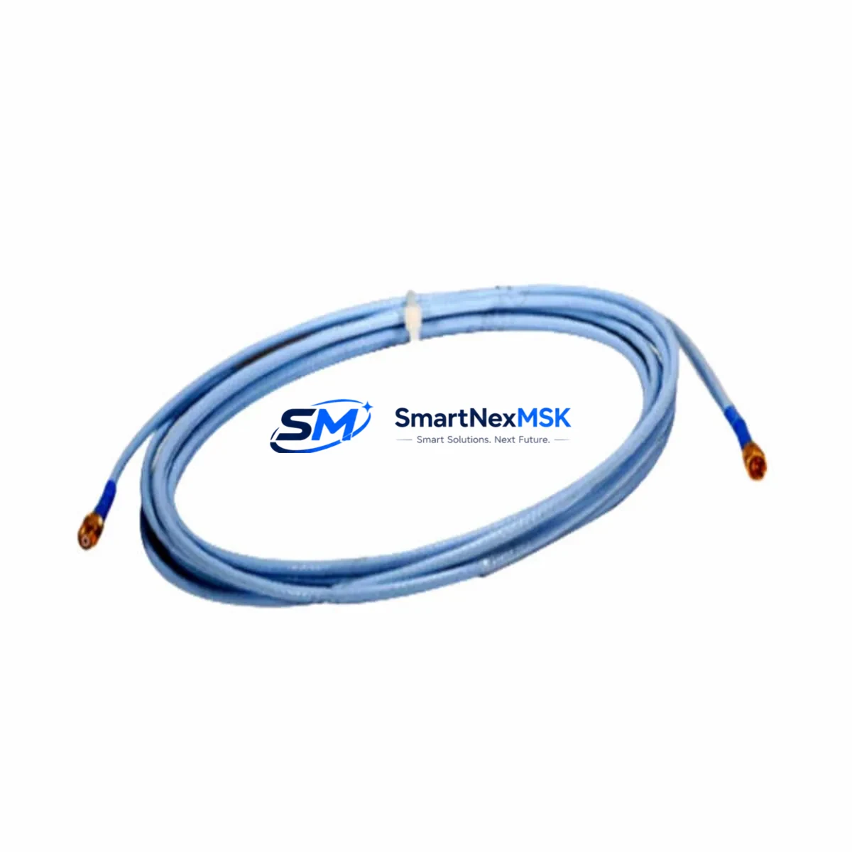
Bently Nevada 330930-040-02-00 Retrofit-Ready Extension Cable for 3300 Series Control Systems
The Bently Nevada 330930-040-02-00 is a 40-foot (12.2 m) armored extension cable engineered for use with the Bently Nevada 3300 Series proximity transducer system — one of the most widely deployed vibration monitoring platforms in rotating machinery protection. As legacy installations age and OEM support for original cabling assemblies becomes increasingly limited, this cable serves as a verified drop-in retrofit replacement, enabling maintenance teams to restore full system functionality without redesigning the transducer loop or modifying the monitor rack.
Whether you are replacing a damaged cable on a running turbine train, upgrading a deteriorated wiring harness during a planned outage, or rebuilding a 3300 Series monitoring loop from a decommissioned asset, the 330930-040-02-00 delivers the electrical characteristics, connector compatibility, and mechanical protection required for continuous, reliable proximity measurement in demanding industrial environments.
Upgrade Compatibility Table
| Parameter | Details |
|---|---|
| SKU / Part Number | 330930-040-02-00 |
| Brand | Bently Nevada |
| Compatible Series | Bently Nevada 3300 Series Proximity Transducer System |
| Cable Length | 40 ft (12.2 m) |
| Cable Type | Armored Extension Cable |
| Connector Interface | Standard 3300 Series coaxial connector — direct plug-in replacement, no adapter required |
| Replaces / Supersedes | OEM 330930-040-02-00; compatible with legacy 3300 XL and standard 3300 monitor loops |
| Installation Requirement | No rack modification required; verify total system cable length does not exceed system specification |
| Communication / Signal | Analog proximity signal (eddy-current); no digital protocol conversion required |
| Commissioning Note | Verify gap voltage at transducer tip after installation; confirm OK/NOT OK relay status at monitor module |
| Warranty | 12 Months — covers manufacturing defects and electrical performance |
Retrofit Planning for Existing Automation Systems
Integrating the 330930-040-02-00 into an existing 3300 Series monitoring loop requires a structured approach to ensure signal integrity and system continuity. The extension cable connects the proximity transducer probe — typically a Bently Nevada 330101 or 330103 series probe — to the proximitor/oscillator driver, such as the Bently Nevada 330180 proximitor. The complete transducer system (probe + extension cable + proximitor) must be matched as a calibrated set; substituting only the extension cable while retaining the original probe and proximitor is the standard retrofit approach and does not require recalibration of the monitor module.
Before installation, maintenance engineers should verify the total cable system length. The 3300 Series supports specific total cable length configurations — typically 5 m, 9 m, or 15 m system lengths — and the extension cable length must correspond to the system calibration. The 330930-040-02-00 (40 ft / 12.2 m) is calibrated for the 15-meter system configuration. Confirm that the Bently Nevada 3300/16-mm or 3300/25-mm proximity transducer probe in use is rated for the same system length.
At the monitor rack level, the cable terminates at the proximitor, which feeds the conditioned signal into the Bently Nevada 3500/40M or 3500/42M proximity monitor module (or equivalent 3300-series monitor card). No changes to the monitor module configuration, channel scaling, or alarm setpoints are required when replacing a like-for-like extension cable. However, after cable replacement, engineers should confirm the DC gap voltage reading at the monitor front panel or via the System 1 condition monitoring software to verify the transducer is operating within the linear range (typically −10 VDC to −18 VDC for standard gap).
For installations where the original cable routing passes through conduit, cable trays, or explosion-proof glands, the armored construction of the 330930-040-02-00 provides mechanical protection against abrasion, crush loads, and chemical exposure. Verify that the existing cable gland fittings are compatible with the cable outer diameter before pulling the new cable through existing conduit runs. In hazardous area installations (Zone 1 / Zone 2 or Class I Division 1 / Division 2), confirm that the cable assembly’s intrinsic safety parameters remain within the associated apparatus documentation for the Bently Nevada 3300 XL proximitor in use.
Where the retrofit is part of a broader control system upgrade — for example, migrating from a standalone 3300 Series monitor to a Bently Nevada 3500 Series rack-based protection system — the extension cable remains compatible, as the 3500 Series uses the same transducer interface standard. In such migrations, the primary integration work involves reconfiguring the 3500/20 Rack Interface Module, updating I/O mapping in the System 1 Evolution software, and verifying communication links to the plant DCS via Modbus TCP or OPC DA/UA gateway modules. The physical transducer loop, including this extension cable, typically requires no modification during such a platform migration.
Downtime Control During System Migration
Minimizing unplanned downtime during extension cable replacement is a primary concern for rotating machinery protection systems, where loss of vibration monitoring may trigger a forced unit trip or require a manual bypass authorization. The following approach is recommended to maintain control continuity and protect original program logic throughout the cable swap:
- Pre-outage preparation: Document the existing gap voltage, vibration amplitude, and phase reference readings from the System 1 or DCS historian before the outage begins. These baseline values serve as the acceptance criteria for post-installation verification.
- Bypass authorization: Coordinate with the control room to place the affected channel in bypass or inhibit mode at the 3500/40M monitor module before disconnecting the cable. This prevents a spurious trip signal from propagating to the turbine protection logic or ESD system during the cable change.
- Cable labeling and connector protection: Label both ends of the new 330930-040-02-00 cable before routing. Use connector dust caps on the coaxial connectors during cable pulling to prevent contamination of the mating surfaces.
- Reconnection and gap verification: After reconnecting the new cable, measure the DC gap voltage at the proximitor output before removing the channel bypass. Confirm the reading is within the calibrated linear range. If the gap voltage is outside specification, adjust the transducer tip gap mechanically before returning the channel to service.
- Alarm and trip setpoint confirmation: After the channel is returned to service, verify that the OK relay at the monitor module is energized and that vibration alarm and danger setpoints are active and correctly displayed in the System 1 Evolution operator interface or the plant DCS faceplate. No changes to the PLC ladder logic, function block program, or HMI tag database are required for a like-for-like cable replacement.
- Post-installation test record: Record the post-installation gap voltage, OK relay status, and vibration baseline in the maintenance management system (CMMS) to support future predictive maintenance trending.
For planned turnaround outages where multiple transducer loops are being replaced simultaneously, pre-staging replacement cables and pre-testing each 330930-040-02-00 cable assembly on a bench test rig (using a calibrated proximitor and a metal target) before the outage window significantly reduces field commissioning time and the risk of discovering a defective cable after the machine is already offline.
Retrofit Support FAQ
Q1: Is the 330930-040-02-00 a direct drop-in replacement for the original Bently Nevada cable?
Yes. The 330930-040-02-00 uses the same coaxial connector interface, cable impedance, and length specification as the original OEM assembly. No adapter, re-termination, or recalibration of the monitor module is required. Simply disconnect the old cable at both the probe and proximitor ends, route and connect the new cable, and verify gap voltage before returning the channel to service.
Q2: Will this cable work with both the 3300 Series and 3500 Series monitor racks?
Yes. The 330930-040-02-00 extension cable is compatible with both the Bently Nevada 3300 Series and 3500 Series proximity monitor platforms, as both systems use the same transducer interface standard. Confirm that the total system cable length (probe + extension) matches the calibration configuration of the proximitor in use.
Q3: What commissioning checks are required after installation?
After connecting the new cable, measure the DC gap voltage at the proximitor output (target: −10 VDC to −18 VDC for standard 3300/3500 Series configurations). Confirm the OK relay is energized at the monitor module. Verify vibration amplitude and phase readings against pre-outage baseline values in System 1 or the DCS historian. Document all readings in your CMMS before closing the work order.
Q4: What warranty coverage is included, and has the cable been tested before shipment?
Every 330930-040-02-00 unit is function-tested prior to shipment and covered by a 12-month warranty against manufacturing defects and electrical performance failures. If a unit fails to meet specification within the warranty period, we provide a replacement or full refund. Contact our technical team with your installation details and test readings for expedited warranty support.
© 2026 SMARTNEXMSK. All rights reserved.
Original Source: https://smartnexmsk.com
Contact: [email protected] | +86 18259474341



