
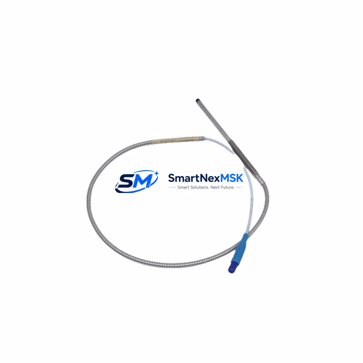
Bently Nevada 330930-040-03-05 Retrofit-Ready Extension Cable for 3300 Series Control Systems
The Bently Nevada 330930-040-03-05 is a 5-metre armored proximity probe extension cable engineered for drop-in compatibility with the Bently Nevada 3300 Series vibration monitoring platform. As legacy machinery protection systems age and OEM spare parts become increasingly scarce, this extension cable serves as a critical link in retrofit projects, discontinued-part replacements, and control-system modernization programs across rotating equipment facilities worldwide.
Whether you are restoring a turbine protection rack, upgrading a compressor monitoring loop, or migrating from an end-of-life 3300/16 monitor to a current-generation 3500 Series rack, the 330930-040-03-05 provides the signal integrity and mechanical durability required for continuous, uninterrupted vibration measurement. Its armored jacket resists oil, coolant, and mechanical abrasion in harsh plant environments, while the precision-matched impedance characteristics ensure compatibility with standard 3300 XL 8mm and 3300 5mm proximity transducer systems.
Upgrade Compatibility Table
| Parameter | Details |
|---|---|
| SKU / Part Number | 330930-040-03-05 |
| Compatible Series | Bently Nevada 3300 Series (3300/16, 3300/20, 3300 XL) |
| Cable Length | 5 metres (armored) |
| Connector Interface | Standard BNC / coaxial, compatible with 3300 Series probe drivers |
| Signal Compatibility | Eddy-current proximity, -24 VDC bias, 200 mV/mil sensitivity |
| Replacement Guidance | Direct drop-in for OEM 330930-040-03-05; verify driver gap voltage after installation |
| Communication Protocol | Analog 4–20 mA / voltage output; no fieldbus conversion required |
| Installation Requirement | Match probe + extension + driver system gap; re-gap at commissioning |
| Commissioning Focus | Gap voltage verification, signal noise floor check, OK relay confirmation |
| Warranty | 12 months from date of shipment |
Retrofit Planning for Existing Automation Systems
Successful retrofit of a Bently Nevada proximity measurement loop requires careful coordination of every component in the signal chain. The 330930-040-03-05 extension cable connects the field-mounted proximity probe — typically a 330103-00-08-10-02-00 or 330780-50-00 probe — to the proximitor driver module housed in the monitor rack. Before installation, engineers must confirm that the existing 3300/16 Monitor or 3300/20 Monitor card accepts the cable’s impedance and that the driver’s gap voltage falls within the -10 VDC to -18 VDC acceptance window.
In control-cabinet upgrade scenarios where a facility is transitioning from a legacy 3300 Series rack to a 3500/42M or 3500/45 monitor module, the extension cable routing and conduit path often remain unchanged — only the termination point at the rack backplane shifts. Technicians should document the existing cable routing, label each extension cable with its channel assignment, and verify that the new monitor’s input impedance matches the probe-driver-extension system’s total capacitance.
For facilities running mixed-generation racks — for example, a 3300/55 Keyphasor module alongside newer 3500 Series I/O cards — the 330930-040-03-05 can bridge the gap, maintaining signal continuity while the broader system migration is staged across planned maintenance windows. Paired with a compatible 330180-X1-05 proximitor driver and a correctly gapped probe, the extension cable restores full channel functionality without requiring PLC program changes or HMI screen reconfigurations, since the analog output signal remains identical to the original specification.
When planning I/O expansion or adding new measurement points to an existing 3300 Series rack, procurement teams should also account for associated components: 3300/20-02-01-00 monitor cards, 330130-080-00-00 proximity probes, 3300/05-01-01-00 power supply modules, and 3300 TDI transient data interface units. Sourcing these components from a single supplier reduces lead time and simplifies incoming inspection and traceability documentation.
Downtime Control During System Migration
Minimizing unplanned downtime is the primary concern in any rotating equipment protection system retrofit. When replacing the 330930-040-03-05 extension cable in a live plant environment, the recommended approach is to pre-stage the replacement cable alongside the existing installation, perform a cold-swap during a scheduled maintenance window, and immediately verify gap voltage and OK relay status before returning the machine to service.
Where a hot-swap or partial-bypass is required to maintain production continuity, technicians can temporarily route the proximity signal through a portable 3300 XL field calibrator to confirm probe and driver health before committing to the full cable replacement. Original PLC ladder logic and HMI trend screens referencing the vibration channel do not require modification, as the 330930-040-03-05 preserves the analog signal format and scaling. Communication links between the monitor rack and the plant DCS — whether via Modbus RTU, 4–20 mA hardwired, or FOUNDATION Fieldbus — remain unaffected by the cable replacement, ensuring that alarm setpoints, trip thresholds, and historian data continuity are maintained throughout the migration.
Post-installation, a structured commissioning checklist should include: gap voltage measurement at the driver terminal, overall vibration baseline comparison against pre-replacement trend data, OK relay output confirmation, and a 30-minute observation period under normal operating load before signing off the work order.
Retrofit Support FAQ
Q1: Is the 330930-040-03-05 a direct replacement for the original Bently Nevada part?
Yes. The 330930-040-03-05 is manufactured to the original Bently Nevada specification and is a direct drop-in replacement. No wiring modifications or driver reconfiguration are required. After installation, perform a standard gap voltage verification to confirm correct probe-driver-extension system alignment.
Q2: Can this extension cable be used with both 3300 XL 8mm and 5mm probe systems?
The 330930-040-03-05 is compatible with the standard 3300 Series coaxial signal chain. Confirm the probe tip diameter and driver model before installation. For 5mm probe systems using a 330191-00-05 driver, verify that the total cable capacitance remains within the driver’s specified range.
Q3: What commissioning steps are required after replacing the extension cable?
After physical installation, measure the gap voltage at the driver output terminal (target: -10 VDC to -18 VDC depending on probe model), confirm the OK relay is energized, check the vibration baseline on the monitor display or DCS historian, and document the as-left gap setting. No PLC program changes or HMI updates are required.
Q4: What warranty and pre-shipment testing does this product carry?
All units carry a 12-month warranty from the date of shipment. Each cable undergoes continuity, insulation resistance, and impedance verification prior to dispatch. A test report is available upon request. In-stock units typically ship within 2–3 business days.
© 2026 SMARTNEXMSK. All rights reserved.
Original Source: https://smartnexmsk.com
Contact: [email protected] | +86 18259474341



