
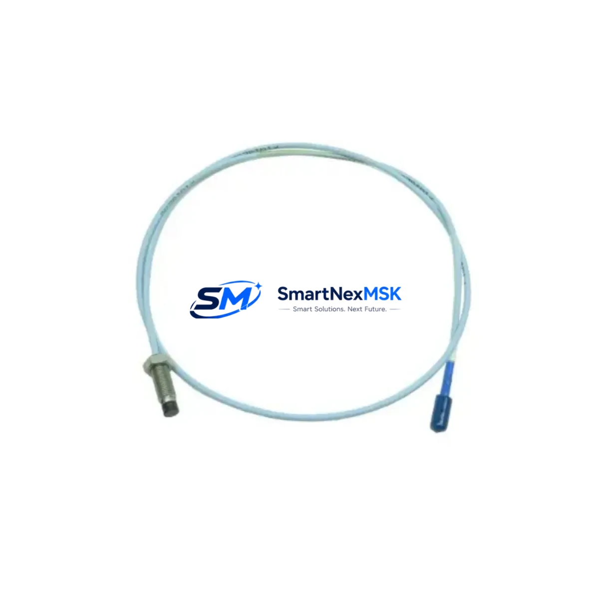
Bently Nevada 330930-045-01-05 Retrofit-Ready Extension Cable for 3300 XL Control Systems
The Bently Nevada 330930-045-01-05 is a 4.5-meter (180-inch) armored extension cable engineered for the 3300 XL proximity transducer system — one of the most widely deployed vibration monitoring platforms in rotating machinery protection. As original equipment reaches end-of-life and spare parts become increasingly scarce, this cable serves as a verified drop-in retrofit replacement for facilities maintaining legacy turbine protection panels, compressor monitoring racks, and critical machinery health systems.
Whether you are executing a planned outage upgrade, responding to an unplanned cable failure, or consolidating your spare parts inventory ahead of a system migration, the 330930-045-01-05 provides a direct solution that preserves your existing wiring topology, signal chain integrity, and monitor calibration — minimizing engineering rework and reducing commissioning time in the field. Each unit ships from in-stock inventory with full continuity and insulation resistance testing completed prior to dispatch, backed by a 12-month warranty from date of shipment.
Upgrade Compatibility Table
| Parameter | Details |
|---|---|
| Part Number | 330930-045-01-05 |
| Brand / OEM | Bently Nevada (Baker Hughes) |
| Series Compatibility | 3300 XL Proximity Transducer System |
| Cable Length | 4.5 m (180 in) |
| Connector Interface | MIL-C-5015 style, compatible with 3300 XL proximitor/driver |
| Signal Type | Eddy-current proximity, −24 VDC bias voltage loop |
| Replaces / Supersedes | 330930-045-01-00, 330930-045-01-02 (earlier suffix variants) |
| Installation Requirement | Verify proximitor housing model (3300 XL 8 mm or 11 mm series) before installation |
| Communication / Protocol | Analog 4–20 mA / voltage output; no fieldbus dependency |
| Commissioning Note | Re-verify gap voltage and scale factor after cable swap; recalibrate if suffix differs from original |
| Warranty | 12 Months from date of shipment |
Retrofit Planning for Existing Automation Systems
Replacing the 330930-045-01-05 in an operating plant requires a structured approach that accounts for the full signal chain — from the probe tip to the monitor rack. In a typical 3300 XL installation, the proximity probe (such as the 330103-00-08-10-02-00 8 mm probe) connects through this extension cable to the 3300 XL proximitor/driver module mounted in the field junction box or directly on the machinery. The proximitor converts the eddy-current signal into a DC voltage proportional to shaft gap, which is then transmitted to the 3300/16 or 3300/20 monitor card housed in the 3300 rack system.
Before pulling the old cable, engineers should document the existing gap voltage reading at the proximitor output — typically between −10 VDC and −18 VDC for a properly gapped 8 mm probe. This baseline reading is critical for post-installation verification. The 3300 rack’s I/O terminal blocks and the field junction box terminal strip should be photographed and labeled before disconnection. If the installation uses a 3500 series monitor as part of a parallel or upgraded monitoring architecture, confirm that the cable routing does not cross into the 3500/42M or 3500/45 module wiring zones to avoid signal interference.
For facilities transitioning from older 7200 series or 3300 non-XL systems to the 3300 XL platform, the extension cable suffix (-05) indicates the armored, oil-resistant jacket variant — essential for installations near bearing housings, seal oil systems, or high-temperature turbine casings. Confirm that the replacement cable’s jacket rating matches the ambient temperature and chemical exposure profile of the installation zone. In hydrogen-cooled generator applications, the cable must be routed through approved conduit with proper sealing glands.
When the retrofit involves a full rack replacement — for example, migrating from a 3300 rack to a 3500 rack with 3500/22M transient data interface cards — the extension cable itself may remain reusable if its length and connector type are compatible with the new proximitor model. However, if the new system uses a 3500/42M enhanced proximitor, verify the input impedance and bias voltage requirements against the cable’s electrical specifications before reuse. In many brownfield upgrades, the 330930-045-01-05 is retained as-is while the monitor cards, 3500/15 power supply modules, and communication gateway modules are replaced.
Facilities using System 1 Evolution or System 1 Optimizer software for condition monitoring should note that cable replacement does not require software reconfiguration, provided the transducer system type and scale factor remain unchanged. If the replacement cable introduces a different total system resistance or capacitance — possible when mixing suffix variants — a new scale factor verification using the 3300 XL calibration procedure is recommended before returning the machine to service.
Downtime Control During System Migration
Minimizing unplanned downtime during a cable replacement or system migration is the primary operational concern for maintenance teams. For the 330930-045-01-05, the recommended approach is to pre-stage the replacement cable, verify its continuity and insulation resistance off-line, and prepare all terminal documentation before the machine is taken offline. In facilities with redundant monitoring channels — common in API 670-compliant installations — the replacement can often be performed on one channel while the redundant channel remains active, allowing the machine to continue operating under reduced monitoring coverage during the swap window.
Program logic in the associated safety system or DCS should be reviewed before the outage. If the vibration monitor output feeds a trip relay or a DCS analog input card, the maintenance team should confirm whether the monitor will generate a fault or trip signal during the cable disconnection interval. Many 3300 XL monitors can be placed in bypass mode via the front-panel keyswitch or through the System 1 software interface, suppressing spurious trips during the maintenance window. This bypass state should be logged, time-stamped, and approved by the control room supervisor before work begins.
After the new cable is installed and the gap voltage is verified, the bypass should be removed and the monitor’s OK relay status confirmed before the machine is restarted. The full commissioning sequence — gap check, scale factor verification, and alarm/trip setpoint confirmation — should be completed and documented in the maintenance management system. For facilities subject to API 670 or IEC 61511 functional safety requirements, a proof test record should be generated and retained as part of the safety instrumented system documentation package.
Retrofit Support FAQ
Q1: Is the 330930-045-01-05 a direct replacement for earlier suffix variants such as -01-00 or -01-02?
In most installations, yes. The -05 suffix denotes the armored jacket variant and is electrically compatible with earlier suffix versions. However, if the original installation used a non-armored cable in a low-exposure environment, verify that the slightly larger outer diameter of the -05 variant fits through existing conduit and cable glands before ordering. Electrical performance and connector interface are identical across suffix variants.
Q2: Do I need to recalibrate the 3300 XL proximitor after replacing the extension cable?
If the replacement cable is the same part number and suffix as the original, recalibration is generally not required — only a gap voltage verification. If the suffix differs, or if the total cable system length changes, a full scale factor verification per the Bently Nevada 3300 XL calibration procedure is recommended. Always document the post-installation gap voltage and compare it to the pre-removal baseline.
Q3: What is the lead time and shipping condition for the 330930-045-01-05?
Units are dispatched from in-stock inventory. Each cable undergoes continuity and insulation resistance testing prior to shipment. Standard export packaging is used for international orders. All units are covered by a 12-month warranty from the date of shipment, covering manufacturing defects and connector integrity.
Q4: Can this cable be used in a 3500 series system or only in the 3300 XL platform?
The 330930-045-01-05 is designed and rated for the 3300 XL proximitor system. While the connector interface may be physically compatible with certain 3500 series proximitor inputs, Bently Nevada specifies dedicated 3500 series cables (such as the 330130 series) for 3500 platform installations. Using a 3300 XL cable in a 3500 system without engineering verification is not recommended and may affect system accuracy and warranty coverage.
© 2026 SMARTNEXMSK. All rights reserved.
Original Source: https://smartnexmsk.com
Contact: [email protected] | +86 18259474341



