
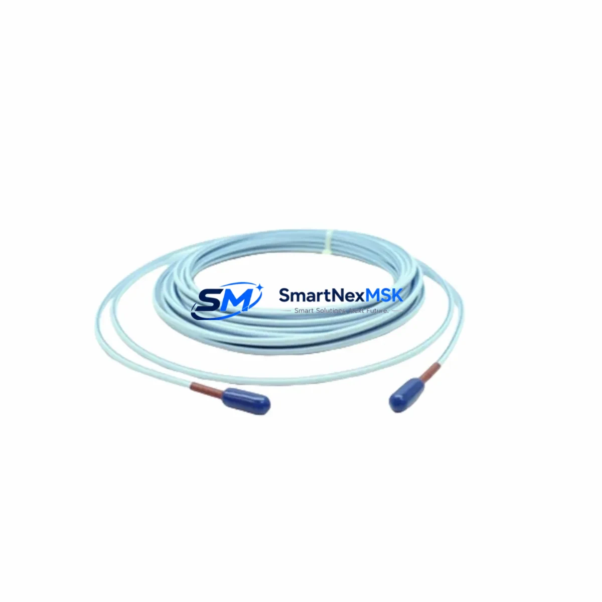
Bently Nevada 330930-065-04-05 Spare for 3300 Series Automation
The Bently Nevada 330930-065-04-05 is an original proximity probe extension cable engineered for the 3300 Series vibration monitoring system — one of the most widely deployed machinery protection platforms in rotating equipment applications worldwide. Whether you are managing a planned maintenance shutdown, responding to an unplanned cable fault, or building a strategic spare parts inventory for a critical turbine or compressor train, the 330930-065-04-05 provides a direct, drop-in replacement that restores full system functionality with zero configuration changes.
Maintenance engineers working on 3300 Series installations understand that the extension cable is a precision component: its electrical length, impedance characteristics, and connector integrity are all calibrated to work in concert with the 3300 XL 8mm proximity transducer and the 3300 Series proximitor sensor. Substituting an uncertified cable introduces gap voltage errors, signal noise, and potential false trips — risks that are unacceptable in turbine protection or compressor monitoring environments. The 330930-065-04-05 eliminates that risk by maintaining the exact electrical specifications required by the system.
Spare Maintenance Table
| Parameter | Specification / Detail |
|---|---|
| Part Number | 330930-065-04-05 |
| Brand | Bently Nevada |
| Series | 3300 Series Proximity System |
| Product Type | Proximity Probe Extension Cable |
| Cable Length | 5.0 m (nominal, per suffix -05) |
| Connector Type | MIL-spec coaxial, armored jacket |
| Compatible Transducer | 3300 XL 8mm Proximity Transducer |
| Compatible Proximitor | 3300 Series Proximitor Sensor |
| Operating Temperature | -40°C to +121°C |
| Installation Environment | Industrial — turbine, compressor, pump, motor bearing housings |
| Replacement Compatibility | Direct drop-in for same-suffix 330930 series cables |
| Commissioning Requirement | Gap voltage verification after installation (typically –10 VDC ±0.5 V) |
| Warranty | 12-Month Warranty — tested before shipment |
| Origin | USA |
| Availability | In stock — ready to ship globally |
Maintenance Planning for Continuous Operation
A well-structured spare parts strategy for a 3300 Series installation goes beyond stocking the extension cable alone. When a 330930-065-04-05 fails or shows signs of jacket damage, connector corrosion, or impedance drift, experienced maintenance engineers use the event as a trigger to inspect the entire measurement chain. The 3300 XL 8mm proximity probe at the machine end should be checked for tip wear and thread integrity. The 3300 Series proximitor sensor mounted in the junction box or rack should be verified for output voltage stability and housing seal condition.
Inside the control cabinet, the 3500/42M Proximitor/Seismic Monitor or equivalent 3500 Series rack monitor card processes the signal from this cable. If the extension cable fault caused a sustained gap voltage alarm, the monitor card’s input circuitry should be inspected before returning the loop to service. The 3500 rack backplane and I/O module connectors are common wear points in high-vibration environments and should be cleaned and re-seated during any cable replacement event.
Power supply integrity is equally important. The 3500 Series power supply module provides the –24 VDC bias voltage that drives the proximity measurement loop. A degraded power supply can cause intermittent gap voltage readings that mimic cable faults — always verify supply output under load before concluding that the cable is the sole fault source. Similarly, the 3500/20 rack interface module and any associated Bently Nevada TDXnet communication gateway should be checked for firmware status and communication link health after a cable replacement.
For facilities running parallel vibration monitoring on multiple machine trains, maintaining a minimum of two 330930-065-04-05 cables per critical machine in the spare parts room is a recognized best practice. Pairing this with a stock of 3300 XL 8mm proximity probes and a set of 3500 Series terminal board connectors ensures that any single-point failure in the measurement chain can be resolved within one shift, keeping unplanned downtime to a minimum.
Site Replacement Workflow
Replacing the 330930-065-04-05 in the field follows a structured sequence that protects both personnel and the monitoring system. Begin by placing the affected channel in bypass mode at the 3500 rack to suppress false trip signals during the cable swap. Document the existing gap voltage reading at the proximitor output before disconnecting — this baseline confirms the probe tip clearance and serves as the acceptance criterion after reinstallation.
Disconnect the old cable at both the proximitor sensor junction box and the probe connector. Inspect the probe tip for mechanical damage before connecting the new 330930-065-04-05. Route the replacement cable following the original cable path, ensuring the armored jacket is not kinked or compressed against sharp edges. Reconnect both ends, restore power to the proximitor, and measure the gap voltage output. A reading within the specified –10 VDC ±0.5 VDC window confirms correct installation. Remove the bypass, verify that the 3500 monitor card shows a healthy channel status, and log the replacement in the maintenance management system.
For systems where the original cable suffix does not match the available spare, confirm that the total system cable length (probe cable + extension cable) remains within the calibrated range for the proximitor model in use. Mismatched total lengths shift the gap voltage curve and require recalibration of the proximitor sensitivity setting — a step that must be performed with the machine at rest.
Spare Parts Support FAQ
Q1: Is the 330930-065-04-05 a direct replacement for other 330930 suffix variants?
The 330930 series uses suffix codes to define cable length and connector configuration. The -065-04-05 suffix specifies a 5-meter armored extension cable with standard MIL-spec coaxial connectors. It is directly interchangeable with cables of the same suffix. Substituting a different length suffix requires verifying that the total probe-plus-extension cable length remains within the proximitor’s calibrated range. Contact our technical team if you need cross-suffix compatibility confirmation before ordering.
Q2: How is the cable tested before shipment?
Every 330930-065-04-05 unit is bench-tested for continuity, insulation resistance, and connector integrity prior to packaging. Units that do not meet original Bently Nevada electrical specifications are rejected. A test report is available upon request. All shipments include a 12-month warranty covering manufacturing defects and electrical performance.
Q3: What is the lead time and can I order multiple units for inventory?
Stock units ship within 1–3 business days. Bulk orders for spare parts inventory programs are supported — contact [email protected] for volume pricing and scheduled delivery arrangements. We maintain long-term supply capability for 3300 Series components to support facilities with extended maintenance cycles.
Q4: What should I check if the gap voltage is still out of range after installing the new cable?
If gap voltage remains outside the –10 VDC ±0.5 VDC window after installing a new 330930-065-04-05, the next diagnostic steps are: (1) verify probe tip clearance at the machine — the physical gap may have changed; (2) check the proximitor sensor output with a calibrated voltmeter to confirm it is responding to the new cable; (3) inspect the 3500 Series power supply module output voltage; (4) confirm the total system cable length matches the proximitor’s calibration. If all checks pass and the reading remains abnormal, the proximitor sensor itself may require replacement or recalibration.
© 2026 SMARTNEXMSK. All rights reserved.
Original Source: https://smartnexmsk.com
Contact: [email protected] | +86 18259474341



