
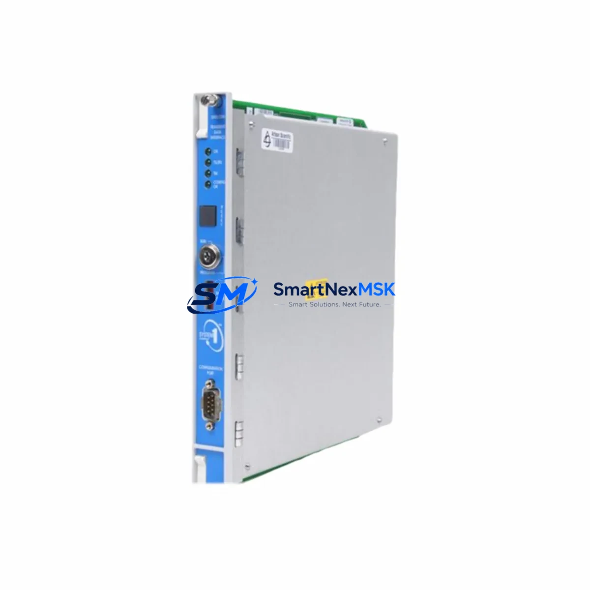
Bently Nevada 3500/32-01-01 Spare for 3500 Automation
The Bently Nevada 3500/32-01-01 (P/N 149986-02 + 125720-01) is a 4-channel relay output module engineered for the Bently Nevada 3500 Series machinery protection system — one of the most widely deployed vibration monitoring and machinery protection platforms in rotating equipment facilities worldwide. Whether you are managing a planned shutdown, responding to an unplanned trip, or building a resilient spare parts inventory for a critical turbine or compressor train, this module is a direct, original-specification replacement that restores full system functionality without reconfiguration or firmware compromise.
For maintenance engineers and reliability teams operating gas turbines, steam turbines, centrifugal compressors, or large pumping systems, the 3500/32-01-01 relay output module serves as the final-stage output interface between the 3500 rack’s monitoring logic and the plant’s alarm and shutdown circuits. Its four independent relay channels can be configured for latching or non-latching operation, supporting both alert and danger setpoint outputs. Sourcing a verified original spare — not a counterfeit or refurbished substitute — is essential to maintaining SIL-rated protection integrity and passing functional safety audits.
Spare Maintenance Table
| Parameter | Specification |
|---|---|
| Part Number | 3500/32-01-01 (149986-02 + 125720-01) |
| Brand | Bently Nevada |
| Series | 3500 Machinery Protection System |
| Module Type | 4-Channel Relay Output Module |
| Relay Channels | 4 independent relay outputs |
| Relay Configuration | Latching / Non-latching (software configurable) |
| Output Rating | 30 VDC / 1 A (resistive load) |
| Rack Compatibility | Bently Nevada 3500 Series rack (standard and enhanced) |
| Communication | Internal rack bus; compatible with 3500/20 rack interface module |
| Operating Temperature | 0 °C to +65 °C |
| Humidity | 5% to 95% RH, non-condensing |
| Installation | Hot-swap capable within powered 3500 rack |
| Configuration Tool | Bently Nevada System 1 / Rack Configuration Software |
| Origin | USA |
| Condition | Original, new or tested-serviceable |
| Warranty | 12 Months |
| Lead Time | Ships within 3–5 business days; expedited available |
Maintenance Planning for Continuous Operation
When a 3500/32-01-01 relay output module is flagged during a control cabinet inspection or fails a functional test, the replacement event should be treated as a system-level review, not an isolated swap. Maintenance engineers should simultaneously verify the condition and configuration of adjacent modules in the same 3500 rack to prevent cascading failures after restart.
Begin by confirming the health of the 3500/20 Rack Interface Module, which manages communication between the rack and the host monitoring system. A degraded rack interface can cause relay outputs to behave erratically even after a module swap. Next, inspect the 3500/15 Power Supply Module — relay output modules are sensitive to supply voltage ripple, and an aging power supply is a common root cause of intermittent relay faults. If the rack includes a redundant power supply configuration, verify that both the primary and secondary 3500/15-02-05 units are within specification.
For the I/O side, check the 3500/40M Proximitor/Seismic Monitor or 3500/42M Proximitor/Seismic Monitor modules that feed vibration data into the relay logic. A misconfigured or drifting monitor module can generate nuisance trips through the relay output even when the relay module itself is healthy. Similarly, review the 3500/50 Tachometer Module if the relay outputs are tied to overspeed or speed-based alarm logic.
On the wiring and terminal side, inspect the field wiring termination at the 3500/32 I/O Module terminal block for signs of oxidation, loose ferrules, or insulation breakdown — particularly in high-vibration or high-humidity environments. Relay output contacts driving external shutdown solenoids or annunciator panels should be tested for contact resistance before the system is returned to service. If the plant uses signal isolators between the 3500 relay outputs and the DCS or safety PLC, verify isolator output integrity as part of the same maintenance window.
For facilities running extended 3500 rack installations, it is also advisable to inspect the 3500/22M Transient Data Interface Module and any installed 3500/60 Temperature Monitor modules during the same cabinet visit, as these share the rack backplane and power bus. Maintaining a minimum of one spare relay output module, one spare power supply, and one spare rack interface module per critical machine train is the recommended inventory posture for facilities targeting less than 4 hours mean time to restore (MTTR) on machinery protection systems.
Site Replacement Workflow
Step 1 — Pre-replacement verification: Before removing the 3500/32-01-01, use Bently Nevada’s Rack Configuration Software (or System 1) to export the current module configuration, including relay setpoints, time delays, latching settings, and channel assignments. Save this configuration file to a secure location — it will be required to restore the replacement module to identical operating parameters.
Step 2 — Safe removal: The 3500 rack supports hot-swap module replacement under most operating conditions. Notify the control room before removal to prevent false alarm interpretation. Loosen the module’s captive screws, disconnect the I/O cable, and slide the module out of the rack slot. Inspect the backplane connector pins for damage or contamination before inserting the replacement unit.
Step 3 — Replacement module installation: Insert the new 3500/32-01-01 into the same rack slot. Reconnect the I/O cable and tighten the captive screws to the specified torque. The rack will automatically detect the new module and apply the stored configuration if System 1 is connected and configured for automatic download.
Step 4 — Configuration restore and functional test: Download the saved configuration to the replacement module. Verify all four relay channels by performing a functional test: simulate alarm and danger setpoints using the rack’s built-in test function and confirm that each relay output operates correctly at the field terminal. Document the test results in the maintenance management system.
Step 5 — Return to service: Confirm with the control room that all relay outputs are reading correctly in the DCS or safety system. Clear any latched alarms generated during the replacement procedure. Update the spare parts inventory record to reflect the consumed module and initiate a replenishment order to maintain minimum stock levels.
This workflow is compatible with both legacy 3500 rack installations and upgraded racks running enhanced firmware. The 3500/32-01-01 is a direct replacement for earlier relay output module variants used in the same series, eliminating the need for rack reconfiguration or setpoint re-entry when the configuration file is preserved.
Spare Parts Support FAQ
Q1: What is the expected service life of the 3500/32-01-01, and when should I plan for proactive replacement?
Bently Nevada relay output modules are designed for continuous industrial service, but relay contact wear and capacitor aging in high-cycle applications typically warrant proactive replacement at 10–15 year intervals or at the first sign of intermittent relay operation. For SIL-rated applications, functional safety proof testing intervals (typically 1–5 years) should include relay contact resistance measurement and operate/release time verification.
Q2: How do I verify compatibility between the 3500/32-01-01 and my existing 3500 rack firmware?
The 3500/32-01-01 is compatible with all standard 3500 rack configurations. Compatibility is confirmed by matching the module’s hardware revision against the rack’s firmware release notes, available through Bently Nevada’s technical documentation. Our team can assist with compatibility verification before shipment upon request.
Q3: What pre-shipment testing is performed on each 3500/32-01-01 unit?
Each unit undergoes functional verification including relay operate/release testing on all four channels, insulation resistance measurement, and visual inspection for connector and PCB integrity before dispatch. A test report is available upon request. All units are shipped in anti-static packaging with protective end caps to prevent transit damage.
Q4: What does the 12-month warranty cover, and what is the return process?
The 12-month warranty covers manufacturing defects and functional failures under normal operating conditions. It does not cover damage resulting from incorrect installation, overvoltage events, or physical mishandling. To initiate a warranty claim, contact our technical support team with the order reference and a description of the fault. Replacement units are dispatched within 5 business days of fault confirmation, minimizing system downtime.
© 2026 SMARTNEXMSK. All rights reserved.
Original Source: https://smartnexmsk.com
Contact: [email protected] | +86 18259474341



