
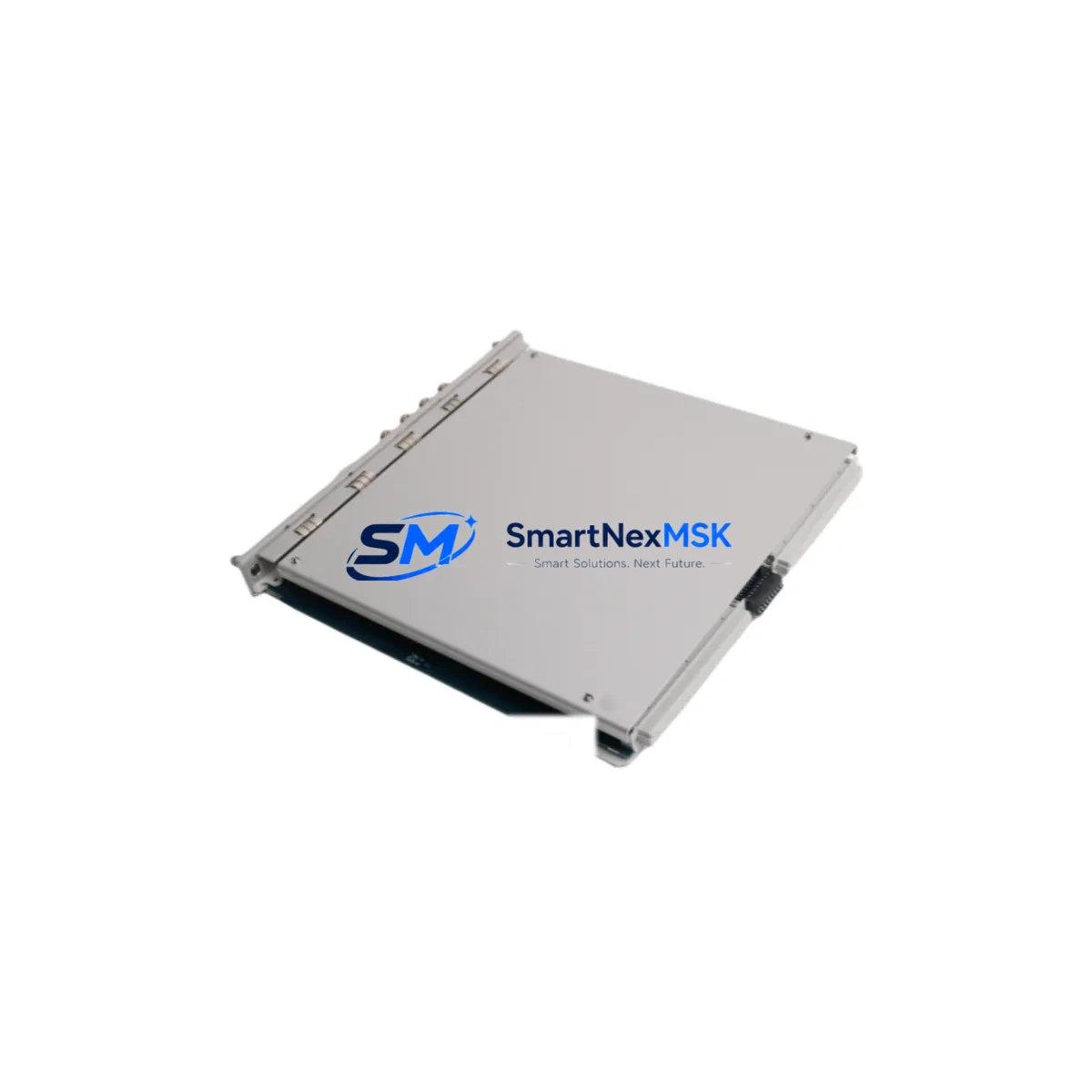
Bently Nevada 3500/33M Retrofit-Ready Relay Output Module for 3500 Series Control Systems
The Bently Nevada 3500/33M is a 16-channel relay output module engineered for the 3500 Series machinery protection system platform. As legacy 3500 Series installations age and original spare parts become increasingly difficult to source, the 3500/33M has become one of the most sought-after retrofit and replacement components for plant engineers managing continuous machinery monitoring systems in oil & gas, power generation, petrochemical, and heavy industrial environments.
Our inventory of the 3500/33M is sourced from verified supply channels, fully tested prior to shipment, and backed by a 12-month warranty. Each unit undergoes functional verification to confirm relay contact integrity, backplane communication, and compatibility with the 3500 Series mainframe before dispatch. Fast global shipping is available with full export documentation support.
Upgrade Compatibility Table
| Parameter | Details |
|---|---|
| Compatible Platform | Bently Nevada 3500 Series Machinery Protection System |
| Module Type | 16-Channel Relay Output Module |
| Backplane Interface | 3500 Series standard backplane slot (I/O rack compatible) |
| Power Supply Compatibility | Compatible with 3500/15 Power Supply Module (standard and enhanced) |
| Communication Protocol | Internal 3500 Series rack bus; supports Modbus RTU via 3500/92 gateway |
| Replacement Recommendation | Direct drop-in replacement for existing 3500/33M installations |
| Installation Requirement | No firmware re-flash required; module address set via rack configuration |
| Commissioning Note | Verify relay trip setpoints in System 1 or Rack Configuration Software after swap |
| Warranty | 12 Months from date of shipment |
Retrofit Planning for Existing Automation Systems
When planning a retrofit or spare-parts replacement involving the 3500/33M, a structured approach to system compatibility is essential to avoid unplanned downtime. The 3500 Series platform is a modular architecture, and the relay output module operates in close coordination with several other rack-resident components.
Begin by auditing the existing rack configuration. The 3500/20 Rack Interface Module governs communication between the host DCS or SCADA and the 3500 rack — confirm that its firmware version supports the relay output configuration you intend to deploy. If the plant is running an older revision of System 1 software, verify that the 3500/33M firmware is compatible before swapping the module.
Power capacity is a critical pre-check. The 3500/15 Power Supply Module must have sufficient headroom to support the relay output module alongside co-installed monitor modules such as the 3500/42M Proximitor/Seismic Monitor or the 3500/45 Position Monitor. Calculate total rack current draw before insertion to avoid nuisance trips or supply brownouts during commissioning.
Terminal wiring on the relay output module uses the standard 3500 Series I/O terminal block format. When replacing an in-service 3500/33M, photograph or document the existing wiring layout before removal. Relay contact assignments — normally open, normally closed, and common — must be re-verified against the original loop drawings. In many retrofit projects, the field wiring remains unchanged, but terminal torque values should be re-confirmed per the installation manual.
For plants migrating from older relay logic panels to the 3500 Series platform, the 3500/33M provides a clean integration path. The module supports both latching and non-latching relay configurations, which is particularly useful when replacing hardwired relay panels in turbine control cabinets. During migration, the 3500/22M Transient Data Interface can be used in parallel to capture pre-migration baseline vibration data, ensuring that post-retrofit alarm setpoints are correctly calibrated.
If the retrofit involves communication protocol migration — for example, moving from a proprietary serial link to Modbus TCP — the 3500/92 Communication Gateway Module should be included in the upgrade bill of materials. This module bridges the 3500 rack to Ethernet-based DCS platforms and is frequently paired with the relay output module in modernization projects. Confirm IP addressing and Modbus register mapping with the DCS engineering team before go-live.
For I/O expansion projects where additional relay outputs are required beyond the existing rack capacity, a secondary 3500 Series rack with its own 3500/15 Power Supply and 3500/20 Rack Interface Module can be added to the system. The 3500/05 Rack (19-inch, 4-slot or 14-slot) provides the physical housing for expansion modules and is fully compatible with the 3500/33M.
HMI integration should also be reviewed during retrofit planning. If the plant uses a GE iFIX, Wonderware, or Ignition SCADA platform, confirm that the relay output status tags are correctly mapped in the OPC-DA or OPC-UA server configuration. In some legacy installations, relay status bits are read via the 3500/92 Modbus map and must be re-mapped after a module swap if the rack slot address changes.
Downtime Control During System Migration
Minimizing unplanned downtime is the primary concern in any 3500 Series relay output module replacement. The recommended approach is a hot-standby swap procedure where the replacement 3500/33M is pre-configured offline using Rack Configuration Software before the maintenance window begins. Pre-load the relay configuration file, verify setpoints, and confirm the module address matches the slot position in the target rack.
During the swap window, inhibit the affected relay channels at the DCS level to prevent spurious trip signals from propagating to the field. Document the inhibit status in the permit-to-work system. Remove the failed or end-of-life module, insert the replacement 3500/33M, and allow the rack to perform its self-test sequence. The module’s front-panel LED indicators will confirm successful initialization.
After insertion, restore relay channel inhibits one at a time, verifying relay contact continuity at the field terminal board before each channel is returned to service. Use a loop calibrator or relay test set to confirm trip and reset thresholds match the original setpoints. If the plant uses System 1 software for centralized monitoring, confirm that the new module is recognized in the rack topology view before closing the maintenance permit.
Original program logic in the DCS or safety system is not affected by a relay output module swap, as the 3500/33M operates as a field output device rather than a programmable controller. However, if the retrofit involves changes to relay assignment or channel mapping, update the DCS I/O configuration and perform a functional test of each relay output before returning the machine train to service.
Retrofit Support FAQ
Q1: Is the 3500/33M a direct drop-in replacement for an existing relay output module in a 3500 Series rack?
Yes. The 3500/33M is designed for direct slot replacement within the 3500 Series mainframe. No hardware modification to the rack or backplane is required. Module address configuration is handled via Rack Configuration Software and does not require physical jumper changes.
Q2: What commissioning steps are required after installing a replacement 3500/33M?
After installation, verify that the module passes the rack self-test (confirmed by front-panel LED status). Re-confirm relay trip setpoints in Rack Configuration Software or System 1. Perform a functional relay test on each channel using a test set before returning to service. Document all setpoint values and test results in the maintenance record.
Q3: Can the 3500/33M be used in a retrofit project migrating from an older relay panel to the 3500 Series platform?
Yes. The 3500/33M supports both latching and non-latching relay configurations, making it suitable for replacing hardwired relay panels in turbine and compressor control cabinets. Field wiring from the existing relay panel can typically be re-terminated directly to the 3500/33M I/O terminal block with minimal modification.
Q4: What warranty coverage is provided, and is pre-shipment testing performed?
Every 3500/33M unit is functionally tested prior to shipment, including relay contact verification, backplane communication check, and visual inspection. A 12-month warranty is provided from the date of shipment, covering manufacturing defects and functional failures under normal operating conditions. Expedited shipping and export documentation are available upon request.
© 2026 SMARTNEXMSK. All rights reserved.
Original Source: https://smartnexmsk.com
Contact: [email protected] | +86 18259474341



