
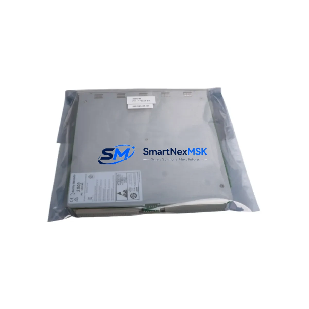
Bently Nevada 3500/45-01-00 Retrofit-Ready Position Monitor for 3500 Series Control Systems
The Bently Nevada 3500/45-01-00 is a dual-channel position monitor designed for seamless integration into the Bently Nevada 3500 Series machinery protection system. Whether you are replacing a failed module, upgrading an aging control cabinet, or migrating from an earlier 3300 Series platform, the 3500/45-01-00 delivers the measurement accuracy, channel density, and rack compatibility that legacy and modern installations demand. SMARTNEXMSK maintains verified stock of this module with full functional testing, 12-month warranty coverage, and expedited global shipping to minimize unplanned downtime on your production line.
Upgrade Compatibility Table
| Parameter | Details |
|---|---|
| Module SKU | 3500/45-01-00 |
| Series Compatibility | Bently Nevada 3500 Series (full rack) |
| Channel Configuration | Dual-channel position monitoring |
| Rack / Backplane Interface | 3500 Series standard backplane slot |
| Power Supply Requirement | Supplied via 3500/15 or 3500/15E power supply module |
| Communication Protocol | System 1 / Modbus RTU / RS-232 (rack-level) |
| Replacement Compatibility | Direct drop-in for 3500/45-01-00; verify firmware revision before swap |
| Installation Requirement | Standard 3500 rack slot; no additional hardware adapter required |
| Commissioning Note | Confirm transducer type, gap voltage, and alert/danger setpoints in System 1 |
| Warranty | 12 months from date of shipment |
Retrofit Planning for Existing Automation Systems
Replacing the 3500/45-01-00 in an operating plant requires a structured approach that accounts for every layer of the machinery protection architecture. Before pulling the module, engineers should document the existing gap voltage readings on each channel using the front-panel BNC test points, and confirm that the paired 3300/16 or 3500/25 proximitor/seismic interface module is still within calibration. If the rack also houses a 3500/20 rack interface module for Modbus or Ethernet communication, verify that the node address and baud rate settings are preserved in the configuration file before any module swap.
Power budget is a critical pre-check. The 3500/15 power supply module supports a defined watt budget across all populated slots; adding or replacing a dual-channel monitor can shift the load balance. Confirm available headroom in the 3500/15 or 3500/15E before proceeding. If the rack is near capacity, a supplemental 3500/15E may be required to maintain stable operation across the 3500/40M radial vibration monitor, 3500/42M velocity monitor, and 3500/45-01-00 position monitor simultaneously.
Terminal wiring on the 3500/45-01-00 follows the standard 3500 Series I/O module pinout. Technicians should photograph or record the existing field wiring on the rear terminal block before removal. Pay particular attention to the OK relay output wiring, which is often connected to the plant DCS or safety PLC for trip logic. If the site uses a 3500/32 4-channel relay module for output voting, confirm that the relay configuration in System 1 software still maps correctly after the module replacement.
For sites migrating from the older Bently Nevada 3300 Series, the 3500/45-01-00 is not a direct pin-compatible replacement for 3300-series monitors. A rack change to the 3500 Series backplane is required, along with re-termination of field cables to the new I/O format. During this migration window, the 3500/22M transient data interface module can be used to capture baseline vibration signatures before the old system is decommissioned, providing a reference dataset for post-migration acceptance testing.
HMI screens connected via the 3500/20 rack interface module or a dedicated OPC-DA/UA server will require tag remapping if the module slot address changes. Coordinate with the control room team to update any System 1 Evolution or third-party SCADA displays that reference the position channel tags before returning the machine to service.
Downtime Control During System Migration
Minimizing production loss during a 3500/45-01-00 swap begins with pre-staging. SMARTNEXMSK ships modules with a factory acceptance test report, allowing the replacement unit to be bench-verified against the original configuration file before the maintenance window opens. Load the existing System 1 configuration backup onto the replacement module in the workshop, confirm that all channel parameters, alert setpoints, and OK relay logic match the as-found condition, and label the module ready for installation.
During the live swap, follow the Bently Nevada recommended power-down sequence: inhibit the trip outputs at the 3500/32 relay module or at the DCS, then remove rack power via the 3500/15 power supply before extracting the monitor. This sequence protects the original program logic stored in the rack interface module and prevents spurious trip signals from reaching the safety system. After installing the replacement 3500/45-01-00, restore power, confirm OK LED status on the front panel, and verify gap voltage on both channels before releasing the trip inhibit.
For critical rotating machinery where a cold shutdown is not acceptable, a parallel rack strategy using a temporary 3500 Series portable rack can maintain continuous monitoring on the machine while the primary rack is serviced. This approach is particularly effective on compressor trains or turbine-generator sets where the 3500/45-01-00 position channel feeds a continuous thrust position trip. Document the parallel monitoring period in the maintenance record and confirm that both racks agree on position readings before decommissioning the temporary setup.
Retrofit Support FAQ
Q1: Is the 3500/45-01-00 a direct replacement for the earlier 3500/45 without the -01-00 suffix?
A: The -01-00 suffix denotes the standard single-ended input configuration. Confirm the input type (single-ended vs. differential) and firmware revision of the original module before ordering. In most 3500 Series installations, the 3500/45-01-00 is a direct functional replacement, but a System 1 configuration upload is recommended after installation to verify all channel parameters are correctly applied.
Q2: What commissioning steps are required after installing the replacement module?
A: After seating the module and restoring rack power, use System 1 software to upload the saved configuration file to the new module. Verify gap voltage on both position channels (typically –10 VDC ±0.5 V for standard Bently Nevada proximity probes), confirm alert and danger setpoints, and perform an OK relay functional test. Record all as-left values in the maintenance log before releasing the machine to operations.
Q3: Can the 3500/45-01-00 be used with non-Bently Nevada proximity probes?
A: The module is optimized for Bently Nevada 3300 XL 8mm and 11mm proximity transducer systems. Third-party probes with compatible sensitivity (nominally 7.87 mV/µm or 200 mV/mil) may function correctly, but full compatibility must be verified against the module’s input specification sheet. SMARTNEXMSK recommends using OEM-matched transducers to maintain measurement accuracy and warranty validity.
Q4: What does the 12-month warranty cover, and how is it claimed?
A: The 12-month warranty covers manufacturing defects and functional failures under normal operating conditions from the date of shipment. Each unit ships with a functional test report. To initiate a warranty claim, contact [email protected] with the order number and a description of the fault. SMARTNEXMSK will arrange return shipping and provide a replacement or repair within the agreed lead time.
© 2026 SMARTNEXMSK. All rights reserved.
Original Source: https://smartnexmsk.com
Contact: [email protected] | +86 18259474341



