
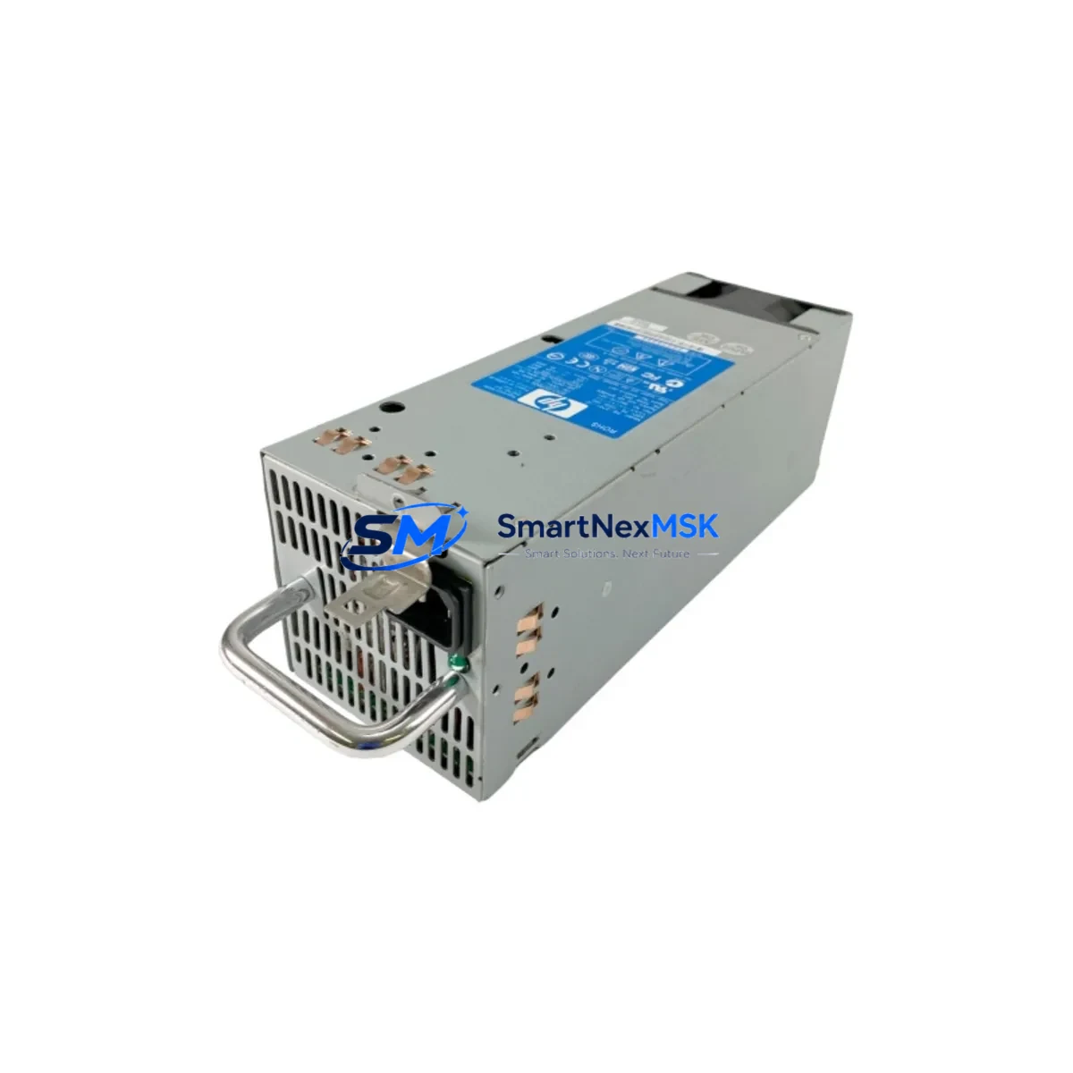
Bently Nevada 3701/60A Retrofit-Ready Condition Monitor for ADAPT Wind Series Control Systems
The Bently Nevada 3701/60A is a high-performance condition monitoring module engineered for seamless integration into ADAPT Wind Series turbine control architectures. As wind energy operators face increasing pressure to extend the operational life of legacy monitoring platforms, the 3701/60A has become the preferred retrofit solution for sites transitioning away from discontinued or end-of-life vibration monitoring hardware. Whether you are replacing a failed module in an existing rack or executing a full control cabinet upgrade, the 3701/60A delivers the measurement accuracy, communication flexibility, and mechanical compatibility required to maintain continuous turbine health monitoring without interrupting production.
Sourced directly from authorized distribution channels and rigorously tested prior to shipment, each 3701/60A unit supplied by SMARTNEXMSK is backed by a 12-month warranty covering both hardware defects and firmware integrity. Our inventory is maintained in climate-controlled storage to preserve calibration baselines, and all units are dispatched with full factory documentation including wiring diagrams, configuration guides, and acceptance test records.
Upgrade Compatibility Table
| Parameter | 3701/60A Specification | Retrofit Notes |
|---|---|---|
| Module Type | Condition Monitoring / Vibration Input | Direct replacement for ADAPT Wind Series monitoring slots |
| Backplane Interface | 3701-series rack backplane | Verify rack revision; 3701/05 rack recommended for full compatibility |
| Communication Protocols | Modbus RTU, PROFIBUS DP, Ethernet/IP (firmware dependent) | Confirm DIP switch and firmware version match site SCADA protocol |
| Power Supply Requirement | 24 VDC, ±5%, max 2.5 A per module | Audit existing 3701/15 or 3701/20 power supply capacity before installation |
| Terminal Wiring | Screw-terminal I/O, 0.5–2.5 mm² conductors | Retain original field wiring; re-terminate per 3701/60A terminal map |
| Module Address | Configurable via Rack Configuration Software (RCS) | Re-assign slot address in RCS to match legacy module position |
| Sensor Compatibility | Eddy-current probes, accelerometers, velocity transducers | Verify transducer bias voltage and sensitivity against 3701/60A input range |
| HMI Integration | System 1 Evolution, Orbit 60 Series | Update HMI tag database and alarm setpoints after module swap |
| Replacement Compatibility | Replaces 3701/60, 3701/55, and select 3500-series monitor functions | Cross-reference I/O count and channel configuration before ordering |
| Warranty | 12 Months | Covers hardware defects, calibration drift, and firmware faults |
Retrofit Planning for Existing Automation Systems
A successful 3701/60A retrofit begins well before the module arrives on site. Engineering teams should start by auditing the existing rack assembly — typically a 3701/05 19-inch rack chassis — to confirm available slot positions, backplane revision, and the current load on the 3701/15 or 3701/20 power supply module. Adding a 3701/60A to a rack that is already operating near its power budget can cause intermittent resets or measurement errors, so a full power audit is a mandatory first step.
Terminal wiring is the next critical checkpoint. The 3701/60A uses a screw-terminal field wiring block that is physically compatible with most ADAPT Wind Series installations, but the terminal assignment map differs from older 3701/55 or 3701/60 modules. Technicians should photograph the existing wiring before disconnection and cross-reference each conductor against the 3701/60A terminal diagram. Eddy-current probe cables, accelerometer signal leads, and velocity transducer outputs must all be re-terminated to the correct input channels to avoid channel-swap faults during commissioning.
Communication configuration is equally important. Sites running Modbus RTU over RS-485 will need to verify baud rate, parity, and device address settings using the Rack Configuration Software (RCS). Sites integrated with a PROFIBUS DP network must update the GSD file in the PLC engineering station — commonly a Siemens S7-300 or S7-400 controller — and re-download the hardware configuration before the 3701/60A will appear on the network. For sites using Ethernet/IP, the module’s IP address must be assigned and the EDS file imported into the control system’s I/O tree.
HMI updates are often overlooked during module replacements. If the site uses System 1 Evolution or an Orbit 60 Series operator interface, the tag database must be refreshed to reflect the new module’s channel assignments and alarm thresholds. Failure to update HMI screens can result in spurious alarms or missed fault indications during the first weeks of operation. Similarly, any historian or data acquisition system connected to the monitoring network should be reconfigured to poll the new module address.
For sites that also need to upgrade adjacent infrastructure, the 3701/60A retrofit is often performed alongside replacement of the 3701/40M keyphasor module, the 3701/44 I/O module, or the 3701/25 communication gateway. In some multi-turbine installations, the upgrade scope extends to the 3500/22M transient data interface or the 3500/42M proximitor monitor, particularly where the site is migrating from a 3500-series rack to the newer 3701 platform. Planning these parallel replacements as a single outage event significantly reduces total downtime compared to sequential module-by-module swaps.
Downtime Control During System Migration
Minimizing turbine downtime during a condition monitoring upgrade requires a structured pre-commissioning strategy. The most effective approach is to pre-configure the replacement 3701/60A module on a bench test rack before the scheduled maintenance window. Using a laptop with Rack Configuration Software installed, technicians can load the site-specific configuration file — including channel assignments, alarm setpoints, transducer parameters, and communication settings — and verify the module’s response to simulated input signals before it ever enters the turbine control cabinet.
During the actual swap, the sequence should follow a defined isolation procedure: disable the affected monitoring channel in the SCADA system, record the current alarm inhibit status, remove the legacy module, install the 3701/60A, and restore power. The entire hot-swap sequence on a properly prepared rack typically takes under 15 minutes per module. Because the 3701/60A retains its configuration in non-volatile memory, there is no risk of losing settings during a power cycle, which protects the integrity of the original program logic and alarm database.
For sites where continuous monitoring is contractually required, a parallel monitoring strategy can be employed: the replacement 3701/60A is installed in an adjacent rack slot and configured to shadow the legacy module’s inputs before the old module is removed. This approach allows the engineering team to validate measurement accuracy and communication integrity under live conditions without interrupting the primary monitoring chain. Once the shadow module is confirmed stable, the legacy module is decommissioned and the 3701/60A assumes primary monitoring responsibility — achieving a zero-gap transition that satisfies both operational and contractual uptime requirements.
Retrofit Support FAQ
Q1: Is the 3701/60A a direct drop-in replacement for the 3701/60 and 3701/55?
The 3701/60A is mechanically and electrically compatible with the same 3701-series rack slots used by the 3701/60 and 3701/55. However, the terminal wiring map and firmware configuration differ between revisions. Always cross-reference the terminal diagram and re-configure the module using RCS before returning the rack to service. Channel count and input type (eddy-current vs. accelerometer) must also be verified against the replacement unit’s specification sheet.
Q2: What communication protocols does the 3701/60A support, and how do I reconfigure after replacement?
The 3701/60A supports Modbus RTU, PROFIBUS DP, and Ethernet/IP depending on firmware version and hardware revision. After installation, use Rack Configuration Software to set the protocol, device address, and baud rate. For PROFIBUS sites, update the GSD file in your PLC engineering environment. For Ethernet/IP, import the EDS file and assign a static IP address. Always perform a full communication test before re-enabling monitoring in the SCADA system.
Q3: How do I verify the replacement module before installation to avoid extended downtime?
All 3701/60A units supplied by SMARTNEXMSK undergo pre-shipment functional testing including power-on self-test, channel response verification, and communication protocol handshake. Upon receipt, customers are advised to perform a bench acceptance test using a signal simulator and a laptop running RCS. This confirms the module’s calibration baseline and communication integrity before it enters the control cabinet, reducing on-site commissioning time to a simple swap-and-verify procedure.
Q4: What does the 12-month warranty cover, and what is the claims process?
The 12-month warranty covers hardware defects, calibration drift beyond factory specification, and firmware faults present at the time of shipment. It does not cover damage resulting from incorrect installation, overvoltage events, or unauthorized firmware modification. To initiate a warranty claim, contact SMARTNEXMSK with the unit serial number, purchase order reference, and a description of the fault. Replacement units are dispatched within 3 business days of claim approval, and defective units must be returned within 30 days for warranty validation.
© 2026 SMARTNEXMSK. All rights reserved.
Original Source: https://smartnexmsk.com
Contact: [email protected] | +86 18259474341



