
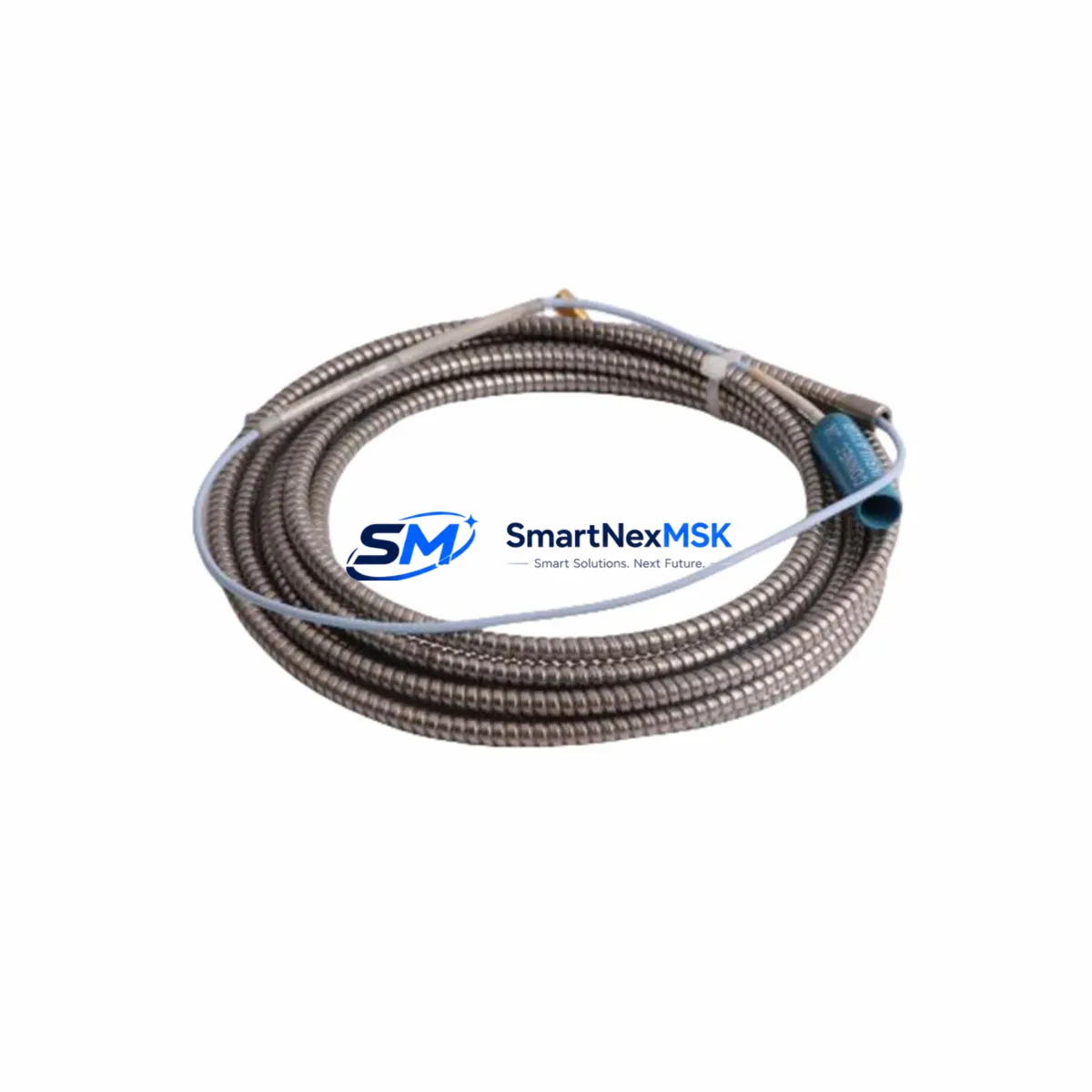
Bently Nevada 84661-60 Retrofit-Ready Velomitor Interconnect Cable for Legacy Control Systems
The Bently Nevada 84661-60 is a Velomitor Interconnect Cable engineered for vibration signal transmission between Velomitor piezo-velocity sensors and Bently Nevada monitoring system racks. As legacy machinery protection systems age and OEM support windows close, the 84661-60 has become a critical retrofit component for engineers tasked with keeping 3300 Series and 3500 Series monitoring platforms operational without full system replacement. Whether you are restoring a discontinued cable assembly, upgrading a degraded signal path, or integrating a new Velomitor sensor into an existing rack, this cable provides a direct, specification-matched replacement that eliminates the need for custom wiring adapters or signal conditioning workarounds.
In retrofit and modernization projects, the 84661-60 is most commonly deployed alongside the Bently Nevada 330500 Velomitor Piezo-Velocity Sensor, which serves as the field-mounted transducer. The cable routes the signal from the sensor back to the monitoring rack, typically terminating at a Bently Nevada 3500/42M Proximitor/Seismic Monitor or a 3300/16 Seismic Monitor input card. Engineers replacing aging cable assemblies should verify the cable length suffix against the original installation drawing — the “-60” designation indicates a 60-inch (approximately 1.5 m) cable, which suits most local panel-to-sensor runs in turbine, compressor, and pump monitoring enclosures.
When planning a retrofit around the 84661-60, the following compatibility and installation factors must be confirmed before commissioning:
- Power supply capacity: Confirm the rack’s internal power supply — typically the Bently Nevada 3500/15 Power Supply — can support the additional current draw if new Velomitor sensors are being added to an existing chassis.
- Terminal block wiring: The 84661-60 uses a standard Bently Nevada connector on the sensor end and bare-wire termination at the rack end. Verify terminal block assignments against the I/O termination drawing for the specific monitor card slot.
- Backplane interface: The 3500 Series uses a 3500/20 Rack Interface Module to manage communication between the monitor cards and the host DCS or safety system. Confirm that the rack interface firmware version supports the monitor card type installed in the slot receiving the 84661-60 signal.
- Module addressing: When replacing a failed card alongside the cable, ensure the replacement 3500/42M or 3500/40M is configured with the correct slot address and channel assignment to match the original Keyphasor and transducer pairing.
- Program and configuration compatibility: Bently Nevada System 1 software stores machine train configuration, alarm setpoints, and transducer scale factors. After replacing the cable and any associated monitor card, re-import the machine configuration file and verify that all setpoints are correctly restored before returning the machine to service.
- HMI screen validation: If the monitoring system feeds a DCS historian or operator HMI — such as a Bently Nevada System 1 Evolution workstation — confirm that the vibration channel tag names and engineering unit scaling are correctly mapped after the retrofit.
- Communication link integrity: The 3500 rack communicates with the plant DCS via Modbus TCP, Profibus, or the proprietary TDI protocol depending on the installed 3500/92 Communication Gateway. After any rack-level hardware change, perform a full communication health check.
- Field commissioning procedure: Before returning the machine to full-speed operation, perform a slow-roll vibration check to confirm baseline signal levels and verify that the Velomitor sensor output is within the expected mV/in/s sensitivity range.
Upgrade Compatibility Table
| Parameter | Detail |
|---|---|
| SKU / Part Number | 84661-60 |
| Brand | Bently Nevada |
| Compatible Series | 3300 Series, 3500 Series Machinery Protection Systems |
| Compatible Monitor Cards | 3500/42M, 3500/40M, 3300/16 Seismic Monitor |
| Compatible Sensor | Bently Nevada 330500 Velomitor Piezo-Velocity Sensor |
| Cable Length | 60 inches (~1.5 m) |
| Connector Type | Bently Nevada standard Velomitor connector (sensor end); bare-wire termination (rack end) |
| Signal Type | Velocity (piezo-velocity, mV/in/s) |
| Installation Requirement | Match terminal block assignment per I/O drawing; verify shield grounding |
| Communication Compatibility | Compatible with 3500/92 Gateway (Modbus TCP, Profibus, TDI) |
| Replacement Recommendation | Direct drop-in replacement for original 84661-60; no adapter required |
| Commissioning Note | Verify slow-roll baseline and System 1 configuration after installation |
| Warranty | 12-Month Warranty — all units tested prior to shipment |
Retrofit Planning for Existing Automation Systems
A successful retrofit involving the 84661-60 rarely involves the cable alone. In most plant environments, the cable replacement is triggered by a broader machinery protection system audit or a forced upgrade following the discontinuation of a legacy monitor card. Engineers typically source the 84661-60 alongside a replacement 3500/42M Proximitor/Seismic Monitor card, a spare 3500/15 Power Supply, and — where the rack interface is also being refreshed — a 3500/20 Rack Interface Module. For plants migrating from the older 3300 platform, the 84661-60 is also compatible with the 3300/16 Seismic Monitor, allowing a phased migration where individual channels are upgraded without requiring a full rack swap.
In compressor train and steam turbine applications, the Velomitor sensor and its interconnect cable are often installed in close proximity to high-temperature surfaces and vibrating pipe runs. Cable routing should follow the original installation path to avoid mechanical fatigue at the connector boot. Where the original cable routing passed through a conduit shared with power wiring, consider installing a dedicated signal conduit to reduce electromagnetic interference — particularly important in plants where the 3500/92 Communication Gateway is transmitting vibration data over Modbus TCP to a DCS historian.
For plants operating Keyphasor-based phase reference systems, the 84661-60 retrofit should be coordinated with a review of the 3500/25 Keyphasor Module configuration to ensure that the phase reference signal is correctly aligned with the new Velomitor channel. Additionally, if the plant uses a Bently Nevada 3500/22M Transient Data Interface for startup and coast-down analysis, confirm that the new cable channel is correctly mapped in the TDI configuration before the next planned startup.
Where the retrofit scope includes I/O expansion — for example, adding a new Velomitor channel to a previously unused rack slot — the engineer must confirm that the rack has sufficient available slots and that the 3500/15 Power Supply capacity has not been exceeded. In multi-rack installations, also verify that the 3500/20 Rack Interface Module in each rack is correctly configured for the plant network topology before commissioning the new channel.
Downtime Control During System Migration
Minimizing unplanned downtime during a Velomitor cable retrofit requires a structured pre-outage preparation process. Before the maintenance window opens, the engineer should download and archive the current System 1 machine configuration, export the active alarm setpoint database, and photograph the existing terminal block wiring at the rack. This documentation ensures that if the replacement 84661-60 or associated monitor card requires re-configuration, the original settings can be restored without relying on memory or incomplete as-built drawings.
During the outage, the recommended sequence is: isolate the affected vibration channel at the rack (place the channel in bypass mode if the 3500 Series rack supports it), disconnect the old cable at both the sensor and rack ends, install the new 84661-60, re-terminate the rack-end wiring per the I/O drawing, and restore the channel from bypass. This sequence keeps the remaining channels in the rack active throughout the cable replacement, preserving machinery protection coverage on all other monitored points. For plants where continuous protection is mandatory — such as API 670-compliant installations — confirm with the operations team whether a temporary portable vibration monitor is required to cover the affected machine during the outage window.
After the new cable is installed and the channel is restored, perform a live signal check using the System 1 software or a handheld calibrator to confirm that the Velomitor output is within the expected range before the machine is returned to service. Document the as-left signal level, the cable installation date, and the technician name in the plant maintenance management system. This record supports future warranty claims and provides a baseline for trending cable degradation over time.
Retrofit Support FAQ
Q: Is the 84661-60 a direct replacement for the original Bently Nevada cable, or does it require an adapter?
A: The 84661-60 is a direct drop-in replacement. It uses the original Bently Nevada Velomitor connector specification on the sensor end and standard bare-wire termination on the rack end. No adapter, signal conditioner, or wiring modification is required for installations that originally used the 84661-60 or a compatible Velomitor interconnect cable.
Q: How do I verify compatibility with my existing 3300 or 3500 Series rack before ordering?
A: Confirm the monitor card type installed in the target slot (3500/42M, 3500/40M, or 3300/16), the Velomitor sensor model (typically 330500), and the required cable length. The “-60” suffix indicates a 60-inch cable. If your installation requires a different length, contact us with your rack drawing and we will confirm the correct part number.
Q: What testing is performed before shipment, and what does the 12-month warranty cover?
A: Every 84661-60 unit is electrically tested for continuity, insulation resistance, and connector integrity before shipment. The 12-month warranty covers defects in materials and workmanship under normal operating conditions. Units that fail within the warranty period are replaced at no charge. Warranty claims require the original order number and a description of the failure mode.
Q: Can the 84661-60 be used in a migration from the 3300 Series to the 3500 Series platform?
A: Yes. The 84661-60 is compatible with both the 3300/16 Seismic Monitor and the 3500/42M, making it suitable for phased migrations where individual channels are upgraded from the 3300 to the 3500 platform without a full rack replacement. During the migration, verify that the System 1 machine configuration is updated to reflect the new monitor card type and that the alarm setpoints are correctly transferred to the 3500 Series channel configuration.
© 2026 SMARTNEXMSK. All rights reserved.
Original Source: https://smartnexmsk.com
Contact: [email protected] | +86 18259474341



