
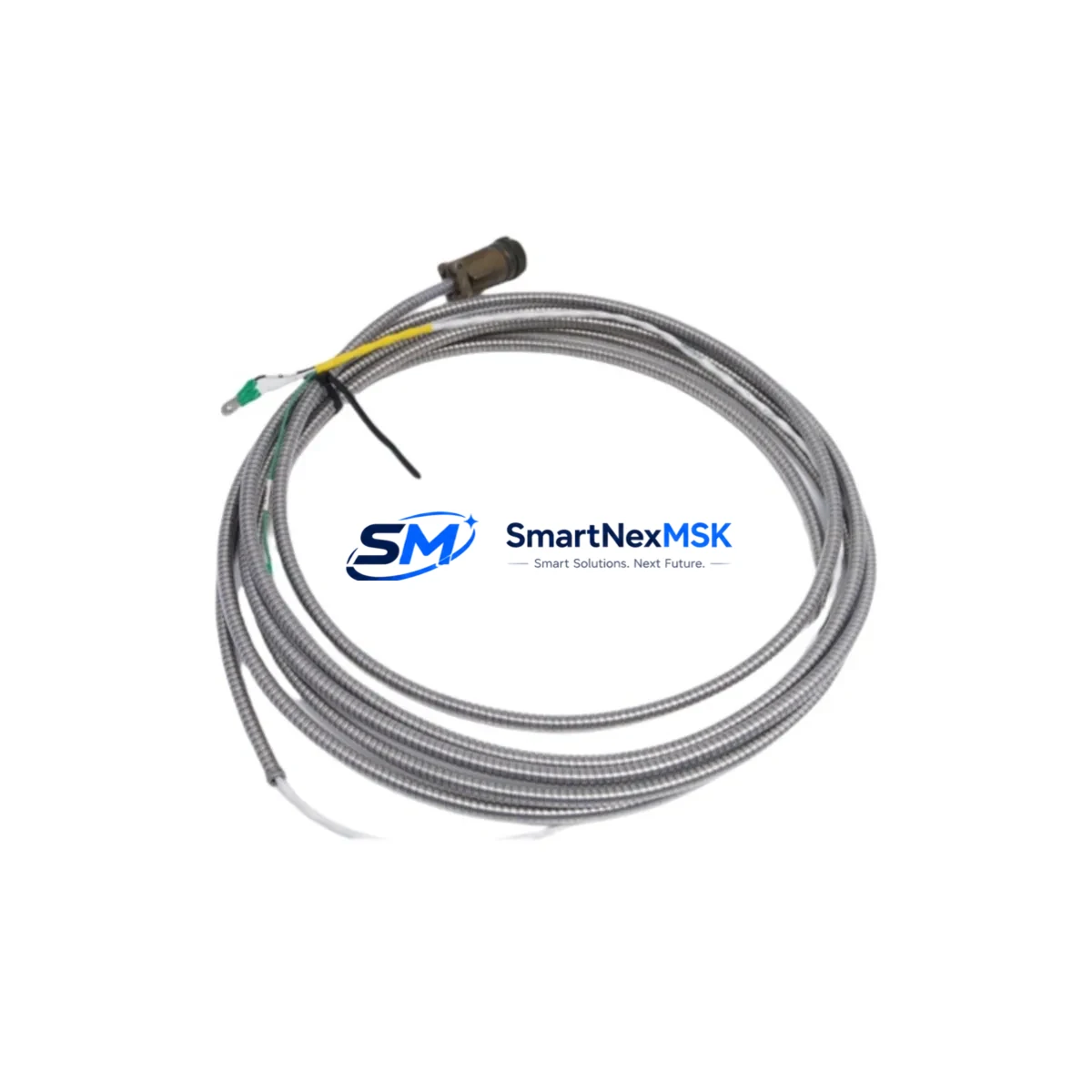
Bently Nevada 84661-75 Spare for Velomitor Automation: Spare Replacement & Industrial Downtime Risk Control
The Bently Nevada 84661-75 is an original Piezo-Velocity Interconnect Cable engineered for the Velomitor series vibration monitoring system. In continuous-process industries — including oil & gas, power generation, petrochemical, and heavy manufacturing — the integrity of vibration signal transmission is non-negotiable. A degraded or failed interconnect cable between the Velomitor sensor and the monitoring rack can produce false alarms, masked fault conditions, or complete loss of machinery protection coverage. Stocking the 84661-75 as a maintenance-ready spare is a fundamental element of any rotating equipment reliability program.
This cable is designed to carry the low-impedance piezo-velocity output signal from the Velomitor transducer to the 3500 Series or 1900 Series monitoring rack with minimal signal attenuation and maximum EMI rejection. Its shielded construction and precision-terminated connectors ensure that velocity readings remain accurate across the full operating frequency range, supporting both alarm setpoint integrity and trend analysis in predictive maintenance programs.
Maintenance engineers and reliability teams working on turbines, compressors, pumps, fans, and gearboxes depend on verified signal paths. When a Velomitor cable is replaced during a planned outage or emergency shutdown, the 84661-75 allows technicians to restore full monitoring coverage quickly, minimizing mean time to repair (MTTR) and reducing the risk of operating machinery without protection.
Spare Maintenance Table
| Parameter | Specification / Detail |
|---|---|
| Part Number / SKU | 84661-75 |
| Brand | Bently Nevada |
| Series Compatibility | Velomitor Piezo-Velocity Sensor Series |
| Product Type | Vibration Monitoring Interconnect Cable |
| Signal Type | Piezo-Velocity (low-impedance output) |
| Connector Type | Precision-terminated, shielded coaxial |
| EMI Protection | Shielded construction for industrial environments |
| Compatible Monitoring Racks | Bently Nevada 3500 Series, 1900 Series |
| Application Environment | Rotating machinery: turbines, compressors, pumps, fans, gearboxes |
| Origin | USA |
| Weight | 660 g |
| Condition | Original, new spare — tested before shipment |
| Warranty | 12 Months |
| Lead Time | In-stock, fast dispatch |
| Maintenance Recommendation | Inspect cable jacket, connectors, and shield continuity at every planned outage. Replace if signal drift or noise floor increase is detected. |
Maintenance Planning for Continuous Operation
When replacing the 84661-75 interconnect cable during a scheduled or emergency maintenance event, a thorough inspection of the surrounding signal chain and power infrastructure is essential to prevent repeat failures and ensure monitoring system integrity. Maintenance engineers should treat cable replacement as an opportunity to audit the full vibration monitoring loop.
Begin by verifying the condition of the Velomitor XA or Velomitor CT transducer itself — connector corrosion, housing cracks, or mounting surface irregularities can introduce signal errors that a new cable alone will not resolve. Check the junction box or field terminal enclosure for moisture ingress, loose terminal screws, and shield grounding continuity. Inspect the 3500/42M Proximitor/Seismic Monitor module or the 1900/65A General Purpose Equipment Monitor input card for bent pins, oxidized contacts, or firmware version mismatches that may affect channel calibration.
On the power side, confirm that the 3500/15 Power Supply module is delivering stable 24 VDC to the rack backplane. A marginal power supply can cause intermittent channel faults that mimic cable failures. If the installation uses a 3500/20 Rack Interface Module (RIM) for Modbus or Ethernet communication, verify that the communication link to the DCS or historian is active and that no watchdog timeouts have been logged.
For installations where the Velomitor feeds into a signal conditioner or signal isolator before entering a third-party DCS input card, inspect the isolator’s input/output terminals and verify its frequency response specification covers the machinery’s operating speed range. In older control cabinets, terminal blocks and DIN rail connectors adjacent to the cable termination points should be checked for thermal cycling damage and retorqued to specification.
Where the vibration monitoring system interfaces with a safety instrumented system (SIS) or machinery protection relay, confirm that the relay trip setpoints and time delays have not drifted and that the relay output contacts are clean and within resistance specification. Finally, update the System 1 Evolution software trend database with the cable replacement date and post-replacement baseline readings to support future predictive maintenance analysis.
Site Replacement Workflow
Step 1 — Isolation & Permit: Obtain a work permit and isolate the monitoring channel per site LOTO procedures. Note the current alarm and danger setpoints from the monitoring rack display or System 1 software before disconnecting any cables.
Step 2 — Cable Removal: Disconnect the 84661-75 at both the Velomitor transducer end and the rack input card end. Inspect the mating connectors on both the transducer and the monitor card for damage, corrosion, or bent pins. Clean with appropriate contact cleaner if required.
Step 3 — New Cable Installation: Route the replacement 84661-75 following the original cable path, maintaining minimum bend radius and avoiding proximity to high-voltage power cables or variable frequency drive (VFD) output conductors. Secure with cable ties at the same support points as the original installation.
Step 4 — Termination & Shield Grounding: Connect the cable at both ends, ensuring the shield is grounded at one end only (typically the rack end) to prevent ground loops. Verify connector seating and locking ring engagement.
Step 5 — Functional Verification: Restore power to the monitoring channel and verify that the DC bias voltage at the transducer output is within the Velomitor specification (typically 8–12 VDC). Confirm that the vibration reading is within expected baseline range for the machine at its normal operating speed. Clear any latched alarms and document the replacement in the maintenance management system (CMMS).
Step 6 — Baseline Update: Record post-replacement vibration amplitude and phase readings as the new baseline in System 1 or the site historian. This establishes a clean reference point for future trend analysis and alarm setpoint review.
Spare Parts Support FAQ
Q1: Is the 84661-75 compatible with both the 3500 Series and 1900 Series monitoring racks?
Yes. The 84661-75 Velomitor interconnect cable is designed for use with Bently Nevada Velomitor series transducers, which are compatible with both the 3500 Series machinery protection system and the 1900 Series general purpose equipment monitors. Always verify the specific cable length and connector configuration required for your installation before ordering.
Q2: What pre-shipment testing is performed on the 84661-75?
Each 84661-75 unit is inspected and tested before dispatch to verify connector integrity, shield continuity, and cable jacket condition. A 12-month warranty is provided from the date of shipment, covering manufacturing defects and component failures under normal operating conditions.
Q3: How should the 84661-75 be stored as a long-term spare?
Store in a clean, dry environment away from direct sunlight, ozone sources, and chemical vapors. Keep in the original packaging or a sealed anti-static bag. Avoid coiling the cable tightly or storing under compression. Inspect connectors annually and apply a light coat of contact protectant if storage exceeds 24 months.
Q4: Can the 84661-75 be used to replace older or discontinued Bently Nevada cable part numbers?
In many cases, yes — provided the connector type, cable length, and impedance characteristics match the original installation requirements. Contact our technical team with your existing part number and installation details for a compatibility confirmation before substituting. We maintain cross-reference records for legacy Bently Nevada cable assemblies to support older system life extension programs.
© 2026 SMARTNEXMSK. All rights reserved.
Original Source: https://smartnexmsk.com
Contact: [email protected] | +86 18259474341



