
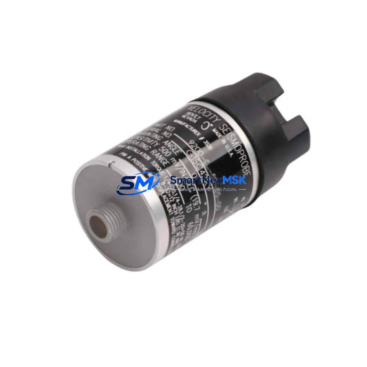
Bently Nevada 9200-09-01-10-00 Retrofit-Ready Eddy-Current Transducer for 9200 Proximitor Control Systems
The Bently Nevada 9200-09-01-10-00 is a two-wire eddy-current transducer engineered for precision proximity measurement in rotating machinery monitoring applications. As legacy 9200 Proximitor systems approach end-of-life or face discontinued spare parts availability, this unit serves as a verified retrofit-ready replacement that preserves signal chain integrity, minimizes rewiring effort, and supports a smooth transition within existing Bently Nevada 3300 and 3500 Series monitoring frameworks. Whether you are managing a planned upgrade cycle or responding to an unplanned component failure, the 9200-09-01-10-00 is stocked and ready for immediate dispatch with a 12-month warranty covering manufacturing defects and functional performance.
Industrial facilities operating turbines, compressors, pumps, and gearboxes that rely on the 9200 Proximitor ecosystem will find this transducer fully compatible with the established signal conditioning architecture. The unit outputs a standard -18 VDC bias voltage at the nominal 200 mV/mil sensitivity, matching the input requirements of the 3300 XL 8mm Proximitor Sensor system and the 3500/42M Proximitor, Seismic, and Velocity Monitor. This compatibility eliminates the need for signal converter modules or intermediate conditioning hardware during the retrofit process, directly reducing both project cost and commissioning time.
Upgrade Compatibility Table
| Parameter | Detail |
|---|---|
| SKU / Part Number | 9200-09-01-10-00 |
| Brand | Bently Nevada |
| Series | 9200 Proximitor |
| Transducer Type | Two-Wire Eddy-Current |
| Sensitivity | 200 mV/mil (7.87 V/mm) |
| Bias Voltage Output | -18 VDC nominal |
| Cable Length | 1.0 m (extension cable required for longer runs) |
| Thread Size | M8 x 1.0 |
| Compatible Monitors | 3300 XL, 3500/42M, 3500/40M, 9200 Proximitor |
| Installation Requirement | Standard 8mm probe mounting boss; no bracket modification required |
| Communication Compatibility | Analog 4–20 mA / voltage output; compatible with DCS and PLC analog input cards |
| Replacement Recommendation | Direct drop-in for 9200-09-01-10-00; verify gap voltage during commissioning |
| Commissioning Focus | Gap voltage setting (typically -10 VDC ± 0.5 V), cable routing, and shield grounding |
| Warranty | 12-Month Warranty — covers manufacturing defects and functional performance |
Retrofit Planning for Existing Automation Systems
Successful integration of the 9200-09-01-10-00 into an existing machinery protection system begins with a thorough pre-installation audit. Engineers should first confirm the available power supply capacity at the junction box or marshalling cabinet. The 9200 Proximitor driver requires a regulated -24 VDC supply, and where the original 9200 Proximitor Extension Cable (part of the 9200 cable set) is being reused, insulation resistance testing is recommended before reconnection to rule out moisture ingress or mechanical damage accumulated over years of service.
Terminal wiring follows the standard Bently Nevada two-wire convention: the center conductor carries the bias signal, and the shield serves as the return path. When migrating from an older 7200 Series probe installation to the 9200 system, technicians must account for the difference in connector type and verify that the 3300 RAM (Rack Adapter Module) or the 3500 rack’s I/O module accepts the updated signal range without rescaling. In systems where the 3500/20 Rack Interface Module manages communication to the plant DCS via Modbus or FOUNDATION Fieldbus, no protocol-level changes are required for the transducer swap itself — the monitor handles signal conversion transparently.
For facilities running a mixed fleet of monitoring hardware, it is common to encounter the 3300 XL 8mm Proximitor Sensor alongside the newer 3500/42M in the same control cabinet. In these environments, the 9200-09-01-10-00 can serve both monitor types without modification, provided the gap voltage is set correctly for each installation point. The 3500 Rack’s configuration is managed through System 1 Evolution software or the legacy System 1 platform, and the transducer replacement does not require a full rack reconfiguration — only the affected channel needs to be taken offline, replaced, and recommissioned.
Where I/O expansion is part of the broader upgrade scope, engineers often simultaneously address the 3500/22M Transient Data Interface or add a 3500/64 Dynamic Pressure Monitor to capture additional process variables. The 9200-09-01-10-00 retrofit can be staged independently of these parallel workstreams, allowing the machinery protection layer to be restored to full operational status before the broader I/O expansion is completed. This staged approach is particularly valuable in continuous-process industries where extended shutdowns carry significant production cost.
Programming compatibility is another key consideration. If the plant historian or safety system reads vibration data from the 3500 rack via OPC-DA or OPC-UA, the tag structure and scaling factors associated with the replaced channel should be verified in the SCADA or DCS configuration after commissioning. HMI screens displaying shaft vibration trends may require a brief engineering review to confirm that alarm setpoints and display ranges remain valid after the transducer swap.
Downtime Control During System Migration
Minimizing unplanned downtime is the primary operational concern when replacing a proximity transducer in a live machinery protection system. The recommended approach is to pre-configure and bench-test the 9200-09-01-10-00 before the maintenance window opens. This includes verifying the static gap voltage output using a calibrated voltmeter and confirming that the transducer’s frequency response is within specification using a signal simulator if available.
During the actual swap, the affected monitor channel should be placed in bypass mode within the 3500 rack to prevent a spurious trip signal from propagating to the emergency shutdown system. The 3500/20 Rack Interface Module supports channel-level bypass without requiring a full rack shutdown, which means adjacent channels monitoring other machine trains remain fully active throughout the procedure. This is a critical advantage over older monitoring architectures that required complete rack power-down for any single-channel maintenance activity.
Once the 9200-09-01-10-00 is physically installed and the gap voltage is confirmed within the acceptable range, the channel bypass is released and the monitor is returned to normal protection mode. The total active intervention time for an experienced technician is typically under two hours, excluding travel and pre-work preparation. Post-installation, a 30-minute observation period is recommended to confirm signal stability before the machine is returned to full load. All commissioning data — gap voltage, bias voltage, cable resistance, and alarm verification results — should be documented in the plant maintenance management system to support future audits and warranty claims.
For facilities with strict change management requirements, the 9200-09-01-10-00 replacement can be fully documented as a like-for-like substitution, which typically qualifies for a simplified management-of-change process rather than a full engineering change order. This further reduces the administrative overhead associated with the retrofit and accelerates the return-to-service timeline.
Retrofit Support FAQ
Q1: Is the 9200-09-01-10-00 a direct replacement for the original Bently Nevada 9200 Proximitor probe, and will it work with my existing extension cable?
A: Yes. The 9200-09-01-10-00 is designed as a direct mechanical and electrical replacement for the original 9200 Series probe. It uses the same M8 x 1.0 thread, the same two-wire signal convention, and the same -18 VDC nominal bias output. Existing 9200 extension cables can be reused provided they pass an insulation resistance check. If the extension cable shows signs of degradation, a replacement 9200 Extension Cable should be sourced simultaneously to avoid a second maintenance intervention.
Q2: What commissioning steps are required after installation, and how do I verify correct gap voltage?
A: After physical installation, connect the transducer to the driver and measure the DC bias voltage at the monitor input terminals using a calibrated voltmeter. The target gap voltage is typically -10 VDC ± 0.5 V, corresponding to a physical gap of approximately 1.0 mm (40 mil) for an 8mm probe. Adjust the probe position in the mounting boss until the target voltage is achieved, then lock the probe in place with the locknut. Verify that the 3500/42M or 3300 XL monitor displays a valid vibration reading before releasing the channel from bypass mode.
Q3: Does replacing the transducer affect my DCS communication or HMI alarm configuration?
A: The transducer replacement itself does not alter the monitor’s communication output. The 3500 rack continues to transmit data via its configured protocol (Modbus, FOUNDATION Fieldbus, or OPC) without interruption. However, it is good practice to verify that the vibration channel’s engineering units, alarm setpoints, and display scaling in the DCS and HMI remain consistent with the new transducer’s calibration data. Any discrepancies should be corrected in the SCADA or DCS configuration before the machine is returned to full load.
Q4: What does the 12-month warranty cover, and what is the process for a warranty claim?
A: The 12-month warranty covers manufacturing defects and functional performance failures under normal operating conditions. It does not cover damage resulting from incorrect installation, overvoltage, mechanical impact, or operation outside the specified environmental limits. To initiate a warranty claim, contact [email protected] with the order number, installation date, and a description of the observed fault. A replacement unit will be dispatched after fault verification, and the defective unit should be returned for inspection. All units are functionally tested prior to shipment to minimize the risk of field failures.
© 2026 SMARTNEXMSK. All rights reserved.
Original Source: https://smartnexmsk.com
Contact: [email protected] | +86 18259474341



