
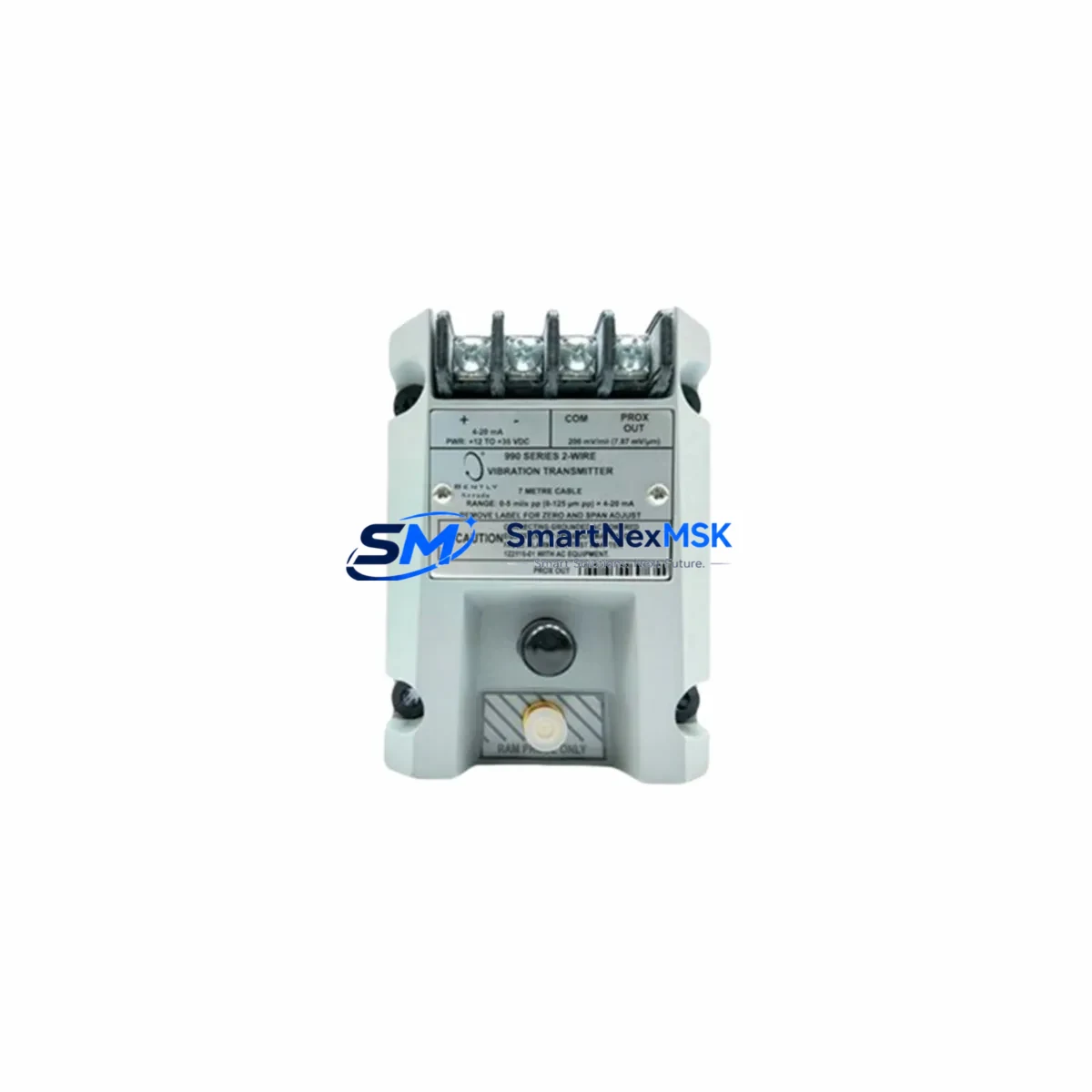
Bently Nevada 990-04-XX-01-00 Retrofit-Ready Vibration Transmitter for 3500 Series Control Systems
The Bently Nevada 990-04-XX-01-00 (also catalogued as 165335-01) is a precision vibration transmitter engineered for seamless integration into Bently Nevada 3500 Series machinery protection systems. As legacy 3300 Series and early 3500 Series installations reach end-of-service milestones, plant engineers and reliability teams increasingly rely on this module to execute drop-in replacements without redesigning the control cabinet or rewriting the protection logic. SMARTNEXMSK maintains verified stock of this transmitter with a 12-month warranty and expedited global shipping to minimize unplanned downtime.
The 990-04-XX-01-00 accepts input from standard Bently Nevada 3300 XL 8mm proximity probes and extension cables, converting raw eddy-current displacement signals into industry-standard 4–20 mA outputs compatible with downstream DCS and safety instrumented systems. Its buffered output also supports direct connection to portable data collectors and online condition monitoring platforms, making it a versatile choice for both permanent installation and temporary bypass configurations during planned outages.
Upgrade Compatibility Table
| Parameter | Details |
|---|---|
| SKU / Part Number | 990-04-XX-01-00 / 165335-01 |
| Compatible System | Bently Nevada 3500 Series Machinery Protection |
| Replaces / Upgrades | 3300 Series transmitters; early 3500 Series vibration monitors |
| Signal Input | Bently Nevada 3300 XL 8mm Proximity Probe + Extension Cable |
| Output Signal | 4–20 mA (isolated); buffered output for data collector |
| Rack / Backplane Interface | 3500 Series 19-slot or 6-slot rack; standard I/O module slot |
| Communication Compatibility | Modbus RTU (via 3500/92 Communication Gateway); System 1 software |
| Power Requirement | 24 VDC from 3500/15 Power Supply Module |
| Installation Requirement | Slot-compatible; verify rack address via 3500 Rack Configuration Utility |
| Commissioning Tool | Bently Nevada 3500 Rack Configuration Software (RCS) |
| Retrofit Recommendation | Retain existing probe and cable; replace transmitter module only |
| Warranty | 12 Months — covers manufacturing defects and functional failure |
Retrofit Planning for Existing Automation Systems
A successful retrofit begins well before the module arrives on site. When replacing the 990-04-XX-01-00 in an operating plant, the first step is to audit the existing 3500/15 Power Supply Module capacity. Each transmitter draws regulated 24 VDC from the rack backplane; if the power supply is already near its rated load — particularly in racks populated with multiple 3500/40M Proximitor Monitor cards and a 3500/92 Communication Gateway — a power budget calculation must be completed before insertion.
Next, document the existing terminal wiring on the 3500 I/O Module associated with the transmitter slot. The 990-04-XX-01-00 uses a standard 25-pin D-sub connector on the I/O module side; confirm that the field wiring from the 3300 XL 8mm Proximity Probe and its matched extension cable terminates correctly at pins 1 (OK relay), 2 (buffered output), and the shield drain. Mislabelled field cables are the most common cause of commissioning delays during 3500 Series retrofits.
Module address configuration is handled through the Bently Nevada 3500 Rack Configuration Software. After physical installation, connect a laptop via the front-panel RS-232 port on the 3500/20 Rack Interface Module and verify that the slot address, channel assignment, and transducer type match the original configuration file. If the plant runs System 1 Evolution condition monitoring software, confirm that the data path from the rack to the historian server remains intact — particularly if the 3500/92 Communication Gateway is configured for Modbus TCP over Ethernet.
For facilities migrating from older 3300 Series racks to the 3500 platform, the 990-04-XX-01-00 serves as the transmitter anchor for the new rack while the 3500/22M Transient Data Interface captures startup transient data for rotor dynamic analysis. Pair the transmitter with a calibrated 3300 XL 8mm Proximity Probe System (probe, extension cable, and Proximitor sensor) to maintain measurement traceability. Where I/O expansion is required — for example, adding axial position monitoring alongside radial vibration — the 3500/45 Position Monitor can be installed in an adjacent slot without disrupting the vibration transmitter’s configuration.
HMI screen updates are often overlooked during module swaps. If the plant DCS uses a Honeywell Experion PKS or Emerson DeltaV integration via the 3500/92 gateway, verify that the Modbus register map for the replacement transmitter matches the original. Tag renaming or register offset changes will cause alarm suppression or false trips on the operator console. Coordinate with the control system engineer to update the HMI faceplate before the replacement module goes live.
Downtime Control During System Migration
Minimizing production impact during a 3500 Series transmitter replacement requires a structured hot-swap protocol. Begin by placing the affected channel in bypass mode using the 3500 Rack Configuration Software — this suppresses the channel alarm output without disabling adjacent channels or the rack’s overall protection logic. The bypass state is time-stamped and logged by the rack, providing an auditable record for safety compliance.
Before removing the existing module, export the full rack configuration file from the 3500/20 Rack Interface Module and store it on a secure network drive. This file contains all setpoint values, time delays, relay logic assignments, and transducer scale factors. If the replacement 990-04-XX-01-00 is loaded with a factory-default configuration, the saved file can be downloaded in under five minutes, restoring the original protection parameters without manual re-entry.
Physical module swap on a 3500 rack is tool-free: release the front-panel locking lever, slide the old module out, insert the replacement, and re-engage the lever. The backplane connector is keyed to prevent incorrect orientation. After insertion, the rack performs a self-test sequence; monitor the module status LED — solid green confirms successful initialization. Re-enable the channel in the RCS software, verify the OK relay output, and confirm the 4–20 mA signal at the DCS input card before removing the bypass. Total elapsed time from bypass activation to channel restoration is typically 15–30 minutes for a prepared team, keeping unplanned downtime to an absolute minimum.
Retrofit Support FAQ
Q1: Is the 990-04-XX-01-00 a direct drop-in replacement for all 3500 Series vibration monitor slots?
A: The 990-04-XX-01-00 is designed for the 3500 Series rack platform and is compatible with standard vibration transmitter slots. However, slot compatibility depends on the specific rack configuration and the I/O module installed. Always verify the slot address and I/O module part number against the rack configuration file before ordering. SMARTNEXMSK’s technical team can assist with compatibility verification based on your rack layout drawing.
Q2: What commissioning steps are required after installing the replacement module?
A: After physical installation, connect to the rack via the 3500/20 Rack Interface Module using the Bently Nevada Rack Configuration Software. Download the saved configuration file, verify transducer type, scale factor, and alarm setpoints, then perform a channel function test by applying a known displacement signal at the probe tip. Confirm the 4–20 mA output at the DCS input and check the OK relay state before releasing the channel from bypass.
Q3: Can the existing 3300 XL proximity probe and extension cable be reused with this transmitter?
A: Yes. The 990-04-XX-01-00 is designed to accept input from the standard Bently Nevada 3300 XL 8mm proximity probe system. Reusing the existing probe and extension cable eliminates the need to re-route field wiring and preserves the calibrated gap voltage established during the original installation. Inspect the cable connector and shield continuity before reuse to rule out field-induced signal degradation.
Q4: What does the 12-month warranty cover, and how is it claimed?
A: The 12-month warranty covers manufacturing defects and functional failure under normal operating conditions. It does not cover damage resulting from incorrect installation, overvoltage, or physical impact. To initiate a warranty claim, contact SMARTNEXMSK with the order number, a description of the fault symptom, and photographic evidence of the installation. Replacement or repair is processed within 5 business days of fault confirmation.
© 2026 SMARTNEXMSK. All rights reserved.
Original Source: https://smartnexmsk.com
Contact: [email protected] | +86 18259474341



