
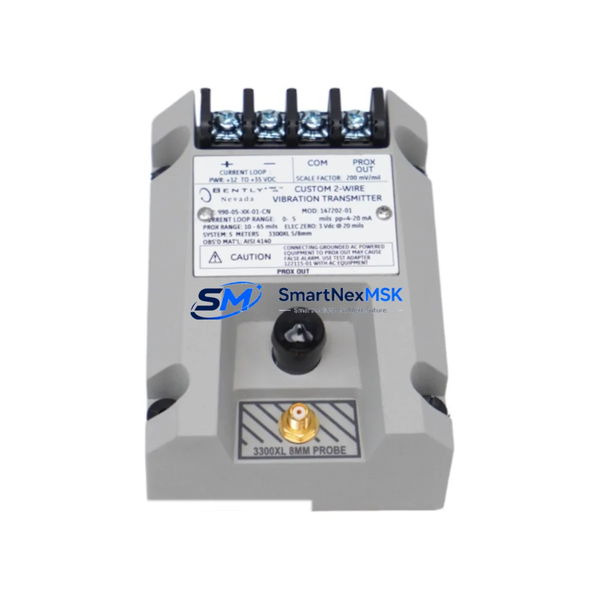
Bently Nevada 990-08-XX-01-CN Retrofit Vibration Transmitter: Compatible Upgrade for 990 Series Control Systems
The Bently Nevada 990-08-XX-01-CN (MOD:163930-02) is a retrofit-ready vibration transmitter engineered for seamless integration into existing 990 Series machinery protection and condition monitoring systems. As legacy Bently Nevada installations approach end-of-support cycles, plant engineers and reliability teams increasingly require a verified, drop-in replacement that preserves original wiring topology, rack addressing, and communication protocol integrity — without forcing a full system overhaul. This module delivers exactly that: a field-proven upgrade path that minimises downtime, protects existing program logic, and restores full monitoring capability to aging control cabinets.
Whether you are replacing a failed unit on a critical rotating machine, upgrading a partial rack to extend system life, or executing a phased migration from an obsolete 990 Series platform to a modern condition monitoring architecture, the 990-08-XX-01-CN provides the electrical and mechanical compatibility required to complete the job with confidence. Each unit ships pre-tested against Bently Nevada factory specifications and is backed by a 12-month warranty covering both parts and workmanship.
Upgrade Compatibility Table
| Parameter | Details |
|---|---|
| SKU / Part Number | 990-08-XX-01-CN MOD:163930-02 |
| Compatible Series | Bently Nevada 990 Series Vibration Monitoring |
| Module Type | Vibration Transmitter / Signal Conditioner |
| Rack / Backplane Interface | Standard 990 Series rack backplane; direct slot replacement |
| Terminal Wiring | Compatible with existing 3300 XL / 990 Series field wiring; no re-termination required in most installations |
| Communication Compatibility | 4–20 mA analog output; compatible with DCS, PLC, and SCADA front-ends accepting standard transmitter signals |
| Power Supply Requirement | Verify rack power module (e.g. 990-05-XX-01-CN power supply) capacity before installation; confirm total rack load does not exceed rated output |
| Replacement Recommendation | Direct replacement for failed or end-of-life 990-08-XX-01-CN units; verify MOD revision compatibility with system firmware |
| Commissioning Notes | Confirm module address DIP switch settings match original unit; validate transducer OK thresholds and alert/danger setpoints in system software after swap |
| Warranty | 12 Months — Parts & Workmanship |
Retrofit Planning for Existing Automation Systems
Successful integration of the 990-08-XX-01-CN into a live plant environment requires careful pre-installation planning across several interdependent system layers. Begin by auditing the existing rack assembly: confirm that the host chassis — typically a 990-01-XX-01-CN or equivalent 990 Series rack — has sufficient available slots and that the backplane bus is free of damage or corrosion. Inspect the rack power supply module to verify that adding or replacing a vibration transmitter card does not push total current draw beyond the rated capacity of the installed power unit.
Field wiring from the proximity probes or accelerometers should be traced back to the terminal block connections on the existing module. In most 990 Series installations, the field wiring can be transferred directly to the replacement 990-08-XX-01-CN without modification, provided the cable shielding and grounding scheme is preserved. If the installation includes a 3300 XL proximitor or a 330180 proximity transducer system, verify that the transducer supply voltage and gap voltage specifications remain within the acceptable range for the replacement module.
For sites running a System 1 condition monitoring software platform or a third-party SCADA front-end, confirm that the 4–20 mA output scaling and the OK relay logic of the replacement module match the configuration expected by the data acquisition layer. Where a Modbus RTU or FOUNDATION Fieldbus communication module — such as a 3500/92 communication gateway — is used to bridge the 990 Series rack to a DCS or historian, validate that the tag mapping and I/O channel assignments remain consistent after the module swap. Any change in channel order or address offset will require a corresponding update in the PLC or DCS I/O configuration, and potentially in the HMI screen tag bindings as well.
If the retrofit is part of a broader migration from the 990 Series to the Bently Nevada 3500 Series machinery protection platform, plan the transition in stages. The 3500/40M proximitor I/O module and the 3500/42M velocity and acceleration I/O module are common targets in such migrations, and their rack and wiring requirements differ from the 990 Series. Retaining the 990-08-XX-01-CN as an interim solution on non-critical monitoring points while migrating critical channels to the 3500 platform allows the plant to maintain continuous protection coverage throughout the upgrade window.
Programming cable compatibility should also be confirmed before on-site work begins. The 990 Series configuration is typically managed through a dedicated configuration software tool connected via a serial or USB-to-serial adapter. Ensure the programming cable and laptop configuration are available on-site before the maintenance window opens, as re-entering setpoints manually without the original configuration file significantly extends commissioning time.
Downtime Control During System Migration
Minimising unplanned downtime during a vibration monitoring module replacement is a primary concern for any reliability or maintenance team. The 990-08-XX-01-CN is designed to support a hot-swap-compatible replacement workflow within the 990 Series rack architecture, but the specific procedure must be validated against the plant’s safety and operational requirements before execution.
Prior to removing the failed or obsolete module, export and archive the full system configuration from the existing rack using the Bently Nevada configuration software. This configuration file preserves all setpoint data, transducer scaling factors, OK relay logic, and communication parameters, and serves as the baseline for post-installation verification. If the original configuration file is unavailable, document all visible setpoint values from the front-panel display or system software before proceeding.
During the physical swap, maintain field wiring continuity where possible by using a temporary bypass or by sequencing the replacement to avoid simultaneous loss of monitoring on multiple channels. After seating the 990-08-XX-01-CN in the rack slot, restore power and allow the module to complete its self-test sequence before reconnecting field wiring. Verify the OK LED status and confirm that the 4–20 mA output is within the expected range for the current machine operating condition before releasing the channel back to the control system.
Post-installation, perform a full functional test: simulate a high-vibration condition using a calibrated signal source if available, and confirm that the alert and danger relay outputs respond correctly. Verify that the System 1 or SCADA historian is receiving valid data on the restored channel, and that no spurious alarms have been generated in the DCS or safety system as a result of the module swap. Document the as-found and as-left conditions in the plant maintenance management system to support future reliability analysis.
Retrofit Support FAQ
Q1: Is the 990-08-XX-01-CN MOD:163930-02 a direct replacement for all 990-08 variants?
The 990-08-XX-01-CN MOD:163930-02 is compatible with the majority of 990-08 series slot positions. However, MOD revision differences may affect firmware compatibility with certain rack configurations. We recommend confirming the MOD revision of the unit being replaced before ordering. Our technical team can assist with cross-reference verification prior to shipment.
Q2: What wiring changes are required during installation?
In most standard 990 Series installations, no field wiring changes are required. The terminal block pinout of the 990-08-XX-01-CN is consistent with the original module design. Verify shield grounding continuity and confirm that the transducer cable is correctly routed and undamaged before reconnecting. If the installation uses a junction box or marshalling cabinet, inspect terminal block labelling to ensure correct channel-to-terminal mapping.
Q3: How is the replacement module commissioned and tested before shipment?
Each 990-08-XX-01-CN unit supplied by SMARTNEXMSK undergoes a pre-shipment functional test that verifies power-up self-test completion, 4–20 mA output linearity, OK relay operation, and physical connector integrity. A test report is available upon request. All units are covered by a 12-month warranty from the date of shipment, covering manufacturing defects and functional failures under normal operating conditions.
Q4: Can this module be used in a mixed 990/3500 Series rack environment?
The 990-08-XX-01-CN is designed exclusively for the 990 Series rack backplane and is not physically or electrically compatible with the Bently Nevada 3500 Series rack architecture. For sites running a mixed monitoring environment, the 990 and 3500 Series racks must be maintained as separate systems. If a full migration to the 3500 platform is planned, contact our team for a phased replacement roadmap that minimises monitoring gaps during the transition.
© 2026 SMARTNEXMSK. All rights reserved.
Original Source: https://smartnexmsk.com
Contact: [email protected] | +86 18259474341



