
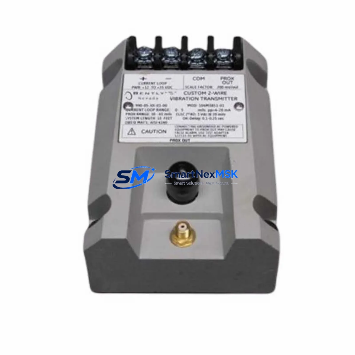
Bently Nevada 990-10-XX-01-00 283278-01 Retrofit-Ready Vibration Transmitter for 3300 Series Control Systems
The Bently Nevada 990-10-XX-01-00 (Part No. 283278-01) is a retrofit-ready vibration transmitter engineered for seamless integration into existing Bently Nevada 3300 Series machinery protection systems. As legacy 3300 XL proximity signal conditioners reach end-of-life and OEM support is discontinued, this module provides a verified drop-in upgrade path that preserves existing wiring infrastructure, rack mounting geometry, and signal output characteristics — minimizing engineering rework and unplanned downtime during system modernization.
Designed for rotating machinery protection in turbines, compressors, pumps, and motors, the 990-10-XX-01-00 delivers 4–20 mA output compatible with both legacy DCS input cards and modern safety instrumented systems (SIS). Whether you are replacing a failed unit on an emergency basis or executing a planned control system upgrade, this module ships pre-tested and ready for immediate installation.
Upgrade Compatibility Table
| Parameter | Details |
|---|---|
| SKU / Part Number | 990-10-XX-01-00 / 283278-01 |
| Brand / Series | Bently Nevada 3300 Series |
| Module Function | Vibration Transmitter / Proximity Signal Conditioner |
| Output Signal | 4–20 mA (industry standard, DCS/SIS compatible) |
| Replaces / Supersedes | 3300 XL Series proximity conditioners; legacy 990-05 variants |
| Rack / Backplane Interface | Compatible with 3300 Series rack backplane; verify slot addressing before installation |
| Power Supply Requirement | 24 VDC nominal; confirm existing PSU capacity before hot-swap |
| Communication Protocol | Analog 4–20 mA; compatible with FOUNDATION Fieldbus gateway adapters |
| Installation Type | Direct rack-mount; no rewiring required for standard 3300 Series cabinets |
| Commissioning Notes | Verify module address, gap voltage, and sensitivity scaling post-installation |
| Warranty | 12-Month Warranty — all units ship fully tested |
Retrofit Planning for Existing Automation Systems
Successful retrofit of the 990-10-XX-01-00 into an operating plant environment requires systematic pre-installation planning. Begin by auditing the existing Bently Nevada 3300 Series rack to confirm available slot positions and backplane revision compatibility. In multi-rack configurations, the rack may also house a Bently Nevada 3300/16 Power Supply or 3300/20 Power Supply — verify that the combined module load does not exceed the PSU’s rated output current before adding or replacing conditioner cards.
Terminal wiring for the 990-10-XX-01-00 follows the standard Bently Nevada barrier terminal block layout. If the existing installation uses a Bently Nevada 3300/55 Proximitor Sensor or 3300/65 Proximitor Sensor as the field transducer, confirm that the driver cable length and gap voltage (typically –10 VDC ± 1 V at nominal gap) fall within the conditioner’s input specification. Deviations in gap voltage are a common source of false alarms during commissioning and must be corrected at the probe tip before the module is placed in service.
For plants migrating from older Bently Nevada 7200 Series or 3500 Series rack architectures, the 990-10-XX-01-00 can serve as an interim signal conditioning stage while the broader migration to a Bently Nevada 3500/42M or 3500/45 position monitor is planned. In these hybrid configurations, the 4–20 mA output feeds directly into the existing DeltaV or Ovation DCS analog input module without protocol conversion, preserving historian continuity and alarm setpoint integrity.
Where the control cabinet also contains a Bently Nevada TDXnet Data Acquisition Module or a System 1 software gateway, confirm that the new conditioner’s channel mapping is reflected in the System 1 configuration database before going live. Failure to update channel tags will result in orphaned trend data and may trigger nuisance alarms in the condition monitoring platform. A Bently Nevada 3300/93 Tachometer or 3300/95 Keyphasor module sharing the same rack should also be re-verified for timing reference integrity after any slot reassignment.
Downtime Control During System Migration
Minimizing production downtime during a vibration monitoring system upgrade requires a structured hot-swap protocol. Where process conditions permit, place the affected machinery protection channel in bypass mode within the DCS or SIS before removing the legacy conditioner. This prevents a spurious trip signal from propagating to the emergency shutdown system (ESD) during the module exchange.
Before pulling the old module, document the existing gap voltage reading, the 4–20 mA loop current at operating speed, and any alarm/danger setpoints configured in the rack or in the System 1 database. These values serve as the baseline for post-installation verification. Once the 990-10-XX-01-00 is seated and the terminal connections are confirmed, restore power and allow a 5-minute warm-up period before re-enabling the protection channel. Compare the live gap voltage and output current against the documented baseline — a deviation of more than ±0.5 VDC or ±0.5 mA warrants probe re-gapping or cable inspection before the bypass is lifted.
All units supplied by SMARTNEXMSK are shipped after full functional testing under simulated load conditions. Each module is accompanied by a test report confirming output linearity, power consumption, and signal noise floor — reducing the risk of infant-failure events that would otherwise extend the maintenance window. The 12-month warranty covers defects in materials and workmanship from the date of shipment, providing assurance for both emergency replacements and planned upgrade projects.
Retrofit Support FAQ
Q1: Is the 990-10-XX-01-00 a direct drop-in replacement for the discontinued 3300 XL proximity conditioner?
A: Yes, for standard 3300 Series rack installations the 990-10-XX-01-00 is mechanically and electrically compatible. Confirm the backplane revision and slot address assignment before installation. No rewiring of the barrier terminal block is required in most cases.
Q2: What commissioning checks are required after installation?
A: Verify gap voltage at the Proximitor sensor (target: –10 VDC ±1 V at nominal gap), confirm 4–20 mA output at known speed or static displacement, check module address in the rack configuration, and update the System 1 or DCS channel tag if applicable. Re-enable the protection channel only after all readings are within specification.
Q3: Can this module be used in a 3500 Series rack or a 7200 Series enclosure?
A: The 990-10-XX-01-00 is designed for the 3300 Series rack backplane. It is not directly interchangeable with 3500 Series I/O modules. For 3500 Series applications, the appropriate replacement is within the 3500/42 or 3500/45 product family. Contact our technical team to confirm compatibility for non-standard configurations.
Q4: What does the 12-month warranty cover, and how is it claimed?
A: The warranty covers manufacturing defects and functional failures under normal operating conditions for 12 months from the shipment date. Each unit ships with a test report. To initiate a warranty claim, contact [email protected] with the order number and a description of the fault. Replacement or repair is arranged within 5 business days of fault confirmation.
© 2026 SMARTNEXMSK. All rights reserved.
Original Source: https://smartnexmsk.com
Contact: [email protected] | +86 18259474341



