
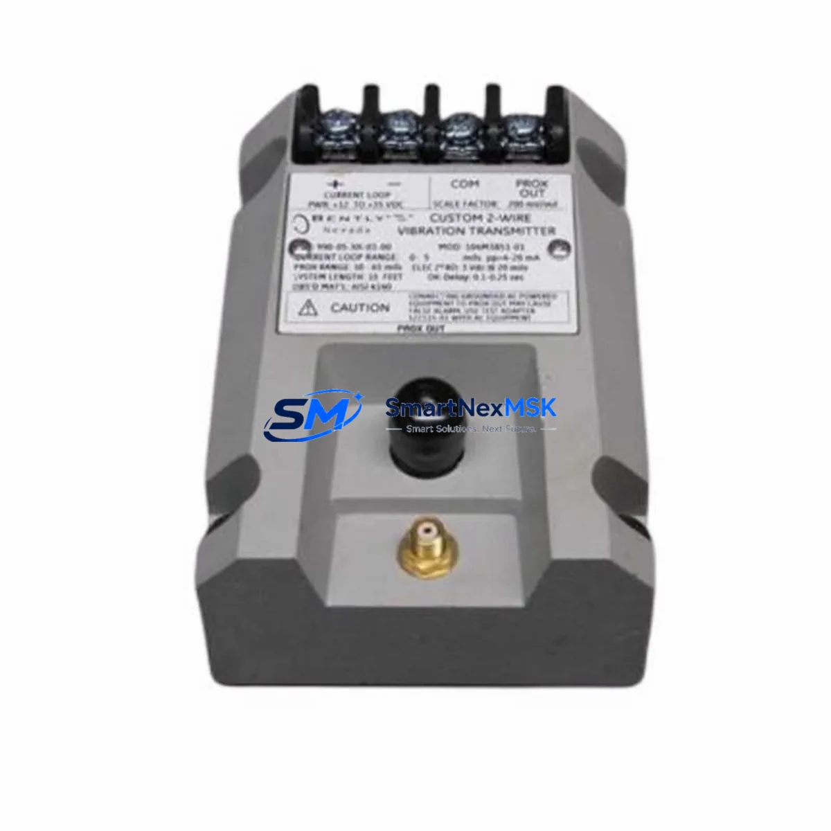
Bently Nevada 990-10-XX-01-CN Maintenance-Ready Spare for 990 Series Automation
The Bently Nevada 990-10-XX-01-CN (Part No. 167541-01) is an original-specification vibration transmitter engineered for continuous rotating equipment monitoring within the 990 Series platform. For maintenance engineers managing turbines, compressors, pumps, and motors in process-critical environments, this module represents a direct, drop-in replacement that restores full system functionality without reconfiguration or firmware changes. Procurement engineers will find this part supported by a 12-month warranty, pre-shipment functional testing, and long-term supply continuity — essential criteria for any approved spare parts list.
Unplanned downtime caused by a failed vibration transmitter can cascade rapidly: loss of machine protection, missed alarm thresholds, and potential equipment damage. Stocking the 990-10-XX-01-CN as a maintenance-ready spare eliminates the lead-time risk associated with OEM procurement channels and keeps your 990 Series protection system fully operational through planned turnarounds and emergency callouts alike.
Spare Maintenance Table
| Parameter | Specification / Detail |
|---|---|
| Part Number | 990-10-XX-01-CN / 167541-01 |
| Brand | Bently Nevada |
| Series | 990 Series Vibration Monitoring |
| Product Type | Vibration Transmitter / Proximitor |
| Output Signal | 4–20 mA (standard industrial loop) |
| Input Compatibility | 3300 XL / 7200 Series proximity probes and extension cables |
| Supply Voltage | 18–30 VDC (loop-powered) |
| Operating Temperature | -40°C to +85°C |
| Enclosure / Housing | DIN-rail or panel-mount compatible |
| Application Environment | Turbines, compressors, pumps, motors — API 670 compliant installations |
| Compatibility | Direct replacement for 990-10-XX-01-CN variants; integrates with 3500 Series rack I/O and DCS analog input cards |
| Origin | USA (Bently Nevada / Baker Hughes) |
| Pre-shipment Testing | Functional output verification performed before dispatch |
| Warranty | 12 Months |
| Lead Time | In-stock; ships within 1–3 business days |
Maintenance Planning for Continuous Operation
When replacing the 990-10-XX-01-CN in the field, a disciplined maintenance engineer will treat the transmitter swap as an opportunity to audit the entire vibration monitoring loop and adjacent control cabinet components. Begin with the 3300 XL proximity probe and its paired 3300 XL extension cable — connector corrosion or cable sheath damage is a common root cause of transmitter overload and premature failure. Verify the proximitor power supply output is within the 18–30 VDC specification before energising the replacement unit.
At the DCS or safety system interface, inspect the 3500/20 rack power supply module and confirm that the analog input card receiving the 4–20 mA signal — typically a 3500/40M proximitor monitor or equivalent I/O module — is free of blown fuses and shows no fault LEDs. Check the terminal block wiring on the field junction box for loose ferrules or oxidised contacts, as high-impedance connections introduce signal noise that can trigger nuisance alarms even after a clean transmitter installation.
For installations where the 990-10-XX-01-CN feeds into a Bently Nevada 3500 Series rack, confirm that the rack’s communication gateway module (e.g., 3500/92 Ethernet or Modbus card) is still synchronising correctly with the plant DCS after the replacement — a transmitter swap can occasionally trigger a rack reset that clears transient alarm states. If the machine train also uses temperature monitoring, cross-check the adjacent 3500/60 temperature monitor inputs to ensure no thermocouple or RTD channels have drifted during the outage window.
For older installations approaching end-of-life, consider scheduling a parallel inspection of the Keyphasor module (3500/25 or equivalent) and any signal conditioner or isolator cards in the same cabinet. These components share the same DC bus and are subject to the same thermal cycling stress as the vibration transmitter. Proactive replacement of aged barrier isolators and surge protection modules during a planned outage is far more cost-effective than an emergency callout triggered by a secondary failure weeks later.
Site Replacement Workflow
Step 1 — Isolation & Permit: Obtain a valid work permit and isolate the machine protection system input for the affected channel. Do not bypass the entire rack — isolate only the channel under maintenance to maintain protection on adjacent machine trains.
Step 2 — Document Baseline: Record the existing transmitter’s output reading (mA value), alarm setpoints, and any active alerts in the DCS historian before disconnection. This baseline is essential for post-installation verification.
Step 3 — Physical Swap: Disconnect the field wiring at the terminal block, noting polarity and shield grounding. Remove the 990-10-XX-01-CN from its mounting. Install the replacement unit, reconnect wiring per the original loop drawing, and verify shield continuity.
Step 4 — Loop Verification: Apply power and confirm the output current falls within the expected 4–20 mA range for the current machine vibration level. Use a calibrated loop calibrator if the machine is offline. Compare against the baseline recorded in Step 2.
Step 5 — System Re-enable & Alarm Check: Re-enable the protection channel in the 3500 rack, confirm no latched alarms, and verify the DCS trend is updating correctly. Document the replacement in the maintenance management system (CMMS) with the new part serial number and installation date.
This workflow minimises total downtime to under two hours for a prepared maintenance team and ensures the replacement 990-10-XX-01-CN is fully validated before the machine is returned to service.
Spare Parts Support FAQ
Q1: Is the 990-10-XX-01-CN a direct drop-in replacement for all 990-10 variants?
The 990-10-XX-01-CN is compatible with standard 990 Series installations using 3300 XL proximity probes. The “-CN” suffix denotes a specific output or configuration variant. Always cross-reference your loop drawing and rack I/O card specification before installation. Our technical team can assist with compatibility verification prior to shipment.
Q2: What pre-shipment checks are performed before dispatch?
Each unit undergoes functional output verification — the 4–20 mA loop is energised and the output signal is confirmed within specification. Units that fail verification are quarantined and not shipped. A test report is available on request for quality-critical procurement.
Q3: How should this spare be stored in a maintenance inventory?
Store in original anti-static packaging in a dry environment between -20°C and +70°C, away from strong electromagnetic fields. Recommended shelf life before re-inspection is 3 years. Label with receipt date and assign a unique spare parts ID in your CMMS for traceability.
Q4: What does the 12-month warranty cover?
The 12-month warranty covers manufacturing defects and functional failure under normal operating conditions from the date of shipment. It does not cover damage caused by incorrect installation, overvoltage, or physical impact. Warranty claims are processed with return authorisation; replacement units are dispatched within 5 business days of confirmed fault diagnosis.
© 2026 SMARTNEXMSK. All rights reserved.
Original Source: https://smartnexmsk.com
Contact: [email protected] | +86 18259474341



