
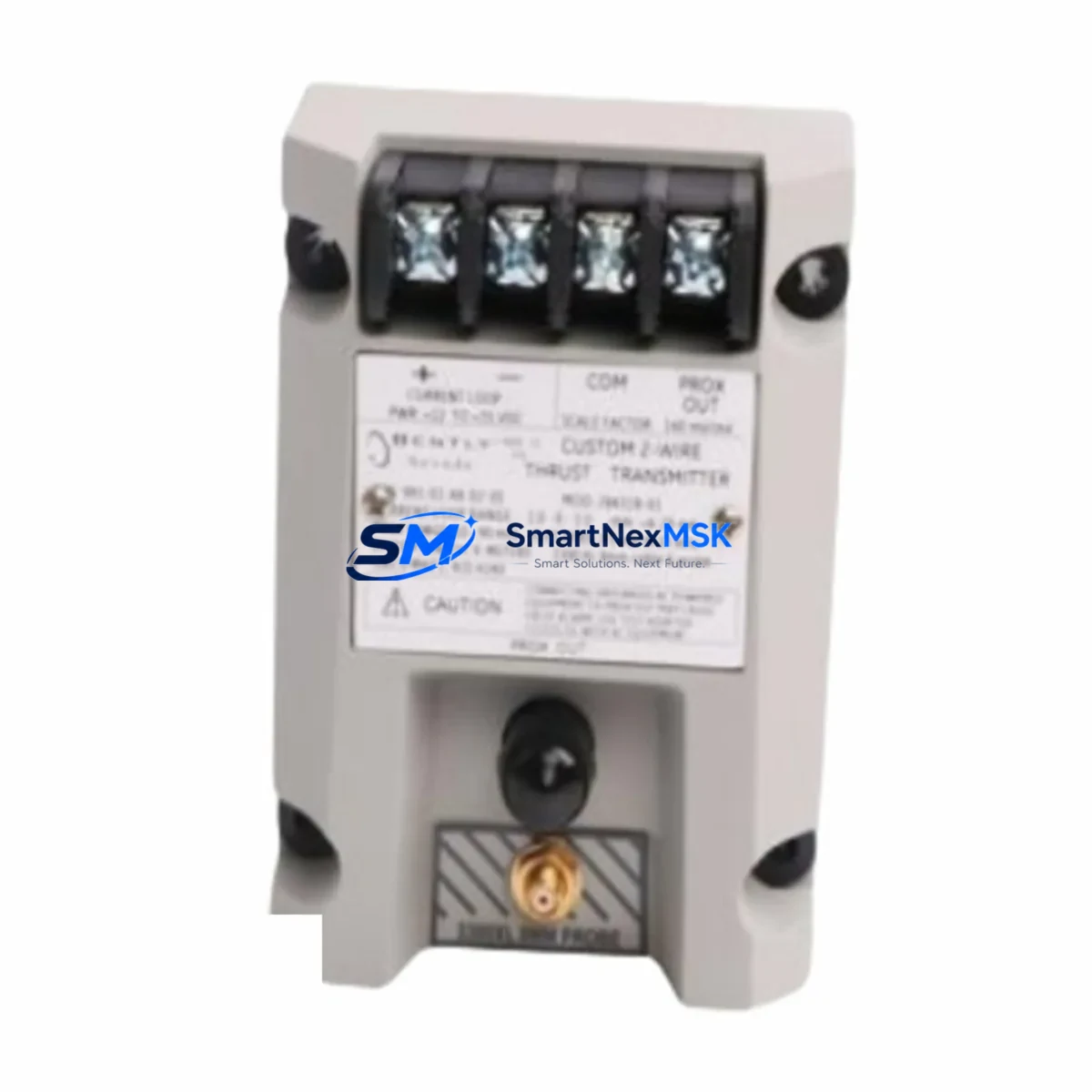
Bently Nevada 991-01-XX-02-05 Maintenance-Ready Spare for 3500 Series Automation
The Bently Nevada 991-01-XX-02-05 is an original vibration transmitter module designed for continuous machinery protection within the Bently Nevada 3500 Series monitoring system. For maintenance engineers managing rotating equipment — turbines, compressors, pumps, and motors — this module is a critical spare that directly impacts uptime and shutdown risk. Unplanned downtime caused by a failed vibration transmitter can cascade into extended outages, especially in facilities where the 3500 rack is the primary protection layer for high-value rotating assets.
This spare is sourced as an original component, fully tested prior to shipment, and backed by a 12-month warranty. It is ready for immediate deployment in planned maintenance windows or emergency replacement scenarios. Whether you are managing a scheduled turnaround, responding to a trip event, or building out your critical spare inventory, the 991-01-XX-02-05 provides the compatibility and reliability your maintenance team requires.
From a procurement perspective, lead times on OEM vibration transmitters can stretch weeks during peak demand. Holding a verified, tested spare on-site eliminates that risk and keeps your protection system fully operational. Our stock is inspected, serialized, and shipped with documentation to support your maintenance records and audit trail.
Spare Maintenance Table
| Parameter | Specification / Detail |
|---|---|
| Part Number | 991-01-XX-02-05 |
| Brand | Bently Nevada |
| Series | 3500 Series Machinery Protection System |
| Module Type | Vibration Transmitter |
| Output Signal | 4–20 mA (standard industrial loop) |
| Input Compatibility | Eddy-current proximity probes (standard Bently Nevada interface) |
| Power Supply | 24 VDC (supplied via 3500 rack backplane) |
| Rack Compatibility | Bently Nevada 3500 Series rack (standard and enhanced) |
| Installation | Plug-in module, DIN-rail compatible rack slot |
| Operating Temperature | 0°C to 65°C (standard industrial environment) |
| Origin | United States (OEM) |
| Condition | Original, tested before shipment |
| Warranty | 12 Months |
| Shipping | Worldwide, with full documentation |
| Maintenance Recommendation | Replace during scheduled turnaround or immediately upon trip/alarm event |
Maintenance Planning for Continuous Operation
When replacing the 991-01-XX-02-05 vibration transmitter in a 3500 Series rack, a thorough maintenance engineer will not stop at the module itself. The replacement event is an opportunity to inspect and verify the health of all interconnected components in the same protection loop and control cabinet.
Start with the 3500/15 Power Supply Module — confirm output voltage is within spec before re-energizing the replaced transmitter. A marginal power supply can cause erratic readings or premature module failure. Next, inspect the 3500/20 Rack Interface Module (RIM), which handles communication between the rack and the host DCS or safety system; a degraded RIM can mask valid vibration alarms even with a healthy transmitter installed.
Check the proximity probe and extension cable assembly (typically Bently Nevada 3300 XL or 7200 Series probes) for cable damage, connector corrosion, and gap voltage. A worn probe or damaged Belden-type extension cable will produce noisy or offset signals regardless of transmitter condition. Verify the Proximitor sensor (driver) output is within the –10 to –18 VDC gap voltage range before declaring the transmitter as the root cause of any alarm.
Within the same cabinet, inspect terminal blocks and field wiring for loose connections, oxidation, and insulation breakdown — particularly on the signal and shield conductors. Review the 3500/22M Transient Data Interface if your system uses waveform capture; a failing TDI can corrupt vibration data and trigger nuisance trips. If your rack includes a 3500/32 4-Channel Relay Module, verify relay contact integrity and setpoint configuration after any transmitter swap.
For facilities running integrated safety systems, confirm that the 4–20 mA output loop to the DCS input card (such as a Yokogawa CENTUM VP AI card or Honeywell C300 analog input) is reading correctly end-to-end after replacement. Signal isolators or loop-powered isolators in the signal path should also be checked for drift. Finally, if the 3500 rack communicates via Modbus or OPC to a SCADA/HMI, verify that the channel mapping and engineering unit scaling are intact after the module swap to avoid false readings at the operator station.
Site Replacement Workflow
Replacing the 991-01-XX-02-05 on-site follows a structured sequence to minimize downtime and ensure system integrity:
1. Pre-replacement verification: Confirm the replacement module part number matches the installed configuration, including the XX position designators which indicate specific output and range options. Cross-reference with your 3500 rack configuration record or the Bently Nevada System 1 software asset database.
2. Safe isolation: Follow your site LOTO procedure. The 3500 rack can often be configured for hot-swap on non-critical channels, but confirm with your system integrator before proceeding on a live rack. For safety-instrumented systems, coordinate with the SIS engineer before bypassing any protection channel.
3. Module extraction and installation: Remove the failed module, inspect the backplane connector for damage or contamination, and seat the replacement firmly. Verify the module status LED sequence on power-up matches the expected initialization pattern.
4. Functional verification: Apply a known reference signal or use the rack’s built-in self-test to confirm the replacement module is reading correctly. Compare live gap voltage and vibration amplitude against baseline records before returning the channel to service.
5. Documentation: Record the replacement in your CMMS (SAP PM, Maximo, or equivalent), update the spare parts inventory, and file the 12-month warranty documentation for the new module.
This workflow supports legacy system life extension — many facilities continue to operate 3500 Series racks well beyond the original design life by maintaining a disciplined spare parts strategy and sourcing verified original replacement modules.
Spare Parts Support FAQ
Q: Is the 991-01-XX-02-05 a direct drop-in replacement for all 3500 Series rack slots?
A: The 991-01-XX-02-05 is designed for specific slot positions within the 3500 rack. The XX designators in the part number indicate output type and range configuration. Always verify your rack configuration record and the installed module’s label before ordering to ensure an exact match. Our technical team can assist with cross-referencing if you provide your rack layout.
Q: What testing is performed before shipment?
A: Every 991-01-XX-02-05 unit is functionally tested prior to shipment, including power-up verification, output signal check, and communication integrity. Units are shipped with a test record and are covered by a 12-month warranty from the date of delivery.
Q: How should I manage inventory for this spare to avoid unplanned downtime?
A: Industry best practice for critical vibration transmitters in continuous-process facilities is to hold a minimum of one spare per rack, with additional units for facilities running multiple 3500 racks. Given OEM lead times, we recommend establishing a replenishment trigger when your on-hand quantity drops to one unit. We support long-term supply agreements for facilities requiring guaranteed stock availability.
Q: Can this module be used to extend the life of an aging 3500 Series system?
A: Yes. Original replacement modules are the most reliable path to extending 3500 Series system life. Using verified OEM spares maintains system certification, preserves alarm setpoint accuracy, and avoids the compatibility risks associated with non-original alternatives. We maintain stock specifically to support legacy system life extension programs.
© 2026 SMARTNEXMSK. All rights reserved.
Original Source: https://smartnexmsk.com
Contact: [email protected] | +86 18259474341



