
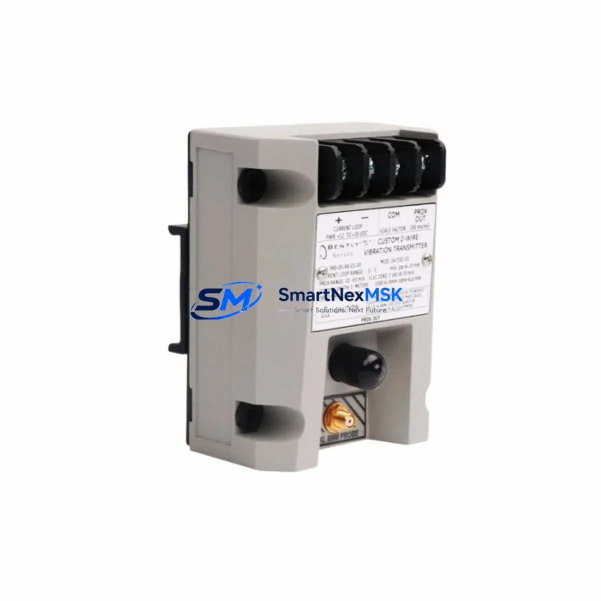
Bently Nevada 991-06-50-01-00 Retrofit-Ready Thrust Position Transmitter for 3500 Series Control Systems
The Bently Nevada 991-06-50-01-00 is a retrofit-ready thrust position transmitter engineered for seamless integration into Bently Nevada 3500 Series machinery protection systems. As legacy monitoring platforms reach end-of-life or require spare-part replenishment, the 991-06-50-01-00 provides a verified drop-in replacement path that preserves existing wiring infrastructure, rack architecture, and software configuration — minimizing engineering rework and unplanned downtime during critical system upgrades.
This transmitter is designed to interface directly with the 3500/42M Proximitor/Seismic Monitor and the 3500/44M Aeroderivative Proximitor Monitor within the 3500 Series rack. It operates on the standard Bently Nevada signal conditioning chain, accepting input from 3300 XL 8mm or 3300 XL 11mm proximity probes and extension cables, and delivering a calibrated 4–20 mA or voltage output to the monitor module. Engineers replacing discontinued 990 Series or early 991 Series transmitters will find the 991-06-50-01-00 fully backward-compatible with existing probe-to-transmitter cable assemblies, eliminating the need for field re-termination in most installations.
When planning a retrofit around the 991-06-50-01-00, the first verification step is confirming power supply capacity within the 3500 rack. The 3500/20 Rack Interface Module governs backplane power distribution, and adding or replacing transmitter modules may require a review of the 3500/15 Power Supply Module’s load budget. Installations running near capacity should audit total module draw before commissioning the replacement unit.
Upgrade Compatibility Table
| Parameter | Details |
|---|---|
| Compatible Rack | Bently Nevada 3500 Series 19″ Rack |
| Compatible Monitor Modules | 3500/42M, 3500/44M, 3500/45 |
| Probe Compatibility | 3300 XL 8mm, 3300 XL 11mm Proximity Probes |
| Signal Output | 4–20 mA / Voltage (configurable) |
| Communication Interface | Backplane bus via 3500/20 Rack Interface Module |
| Replaces / Supersedes | 990 Series Transmitters, Early 991 Series variants |
| Installation Type | DIN rail / rack-mount, no field re-wiring required in most cases |
| Terminal Block Compatibility | Standard 3500 Series I/O terminal block pinout |
| Firmware / Software | Compatible with System 1 Evolution and Rack Configuration Software (RCS) |
| Calibration | Factory pre-calibrated; field verification recommended post-installation |
| Warranty | 12-Month Warranty — covers manufacturing defects and functional performance |
Retrofit Planning for Existing Automation Systems
A successful retrofit centered on the 991-06-50-01-00 requires a structured review of the surrounding system architecture. Begin by documenting the existing rack slot assignment and module address configuration stored in the 3500/20 Rack Interface Module. The module address must be preserved or correctly reassigned in the Rack Configuration Software (RCS) to avoid monitor channel conflicts, particularly in multi-rack installations where the 3500 Series communicates upstream to a DCS or SCADA platform via Modbus TCP or OPC-DA.
Terminal block wiring should be verified against the original I/O drawing. In most 3500 Series installations, the thrust position channel uses a dedicated terminal block on the 3500/42M or 3500/44M monitor module. Confirm that the existing 3300 XL extension cable length and gap voltage are within the transmitter’s specified operating range before energizing the replacement unit. If the original probe-to-transmitter cable assembly has been in service for more than five years, consider replacing it with a new 3300 XL Extension Cable to eliminate signal drift caused by cable degradation.
For plants running Bently Nevada System 1 Evolution as their condition monitoring platform, the 991-06-50-01-00 integrates without requiring a new device driver. The System 1 database retains historical trend data and alarm setpoints, which remain valid after the module swap provided the channel configuration is not altered. HMI screens built on the existing System 1 or third-party SCADA displays will continue to reflect live thrust position data without modification.
In control cabinets where the 3500 rack shares enclosure space with a Bently Nevada 3300 Series monitor or a standalone 990 Series transmitter panel, verify that the cabinet’s thermal load remains within design limits after the retrofit. The 991-06-50-01-00 operates within standard industrial temperature ranges, but dense rack configurations may require additional ventilation review. A 3500/05 Termination Block or 3500/92 Communication Gateway may also be present in the cabinet and should be documented as part of the as-built retrofit record.
Before returning the system to service, perform a full channel functional test: apply a known gap voltage using a calibration simulator, confirm the 4–20 mA output at the monitor module, verify alarm and danger setpoint activation in the System 1 interface, and document the as-found and as-left calibration records. All units shipped by SMARTNEXMSK undergo pre-shipment functional testing to confirm output accuracy and communication integrity prior to dispatch.
Downtime Control During System Migration
Minimizing production downtime during a thrust position transmitter replacement requires advance preparation and a clearly sequenced execution plan. The 991-06-50-01-00’s drop-in compatibility with the 3500 Series rack means that the physical swap can typically be completed within a planned maintenance window of two to four hours, provided all replacement components — including the transmitter, any required 3300 XL extension cables, and terminal block hardware — are staged on-site before the outage begins.
Prior to shutdown, export the current rack configuration from the Rack Configuration Software (RCS) and save a backup of the System 1 database. This preserves all channel scaling, alarm setpoints, and historical trend data, ensuring that the system can be restored to its pre-outage state if any configuration issue arises during commissioning. If the plant operates a redundant 3500 rack configuration, coordinate the replacement sequence to maintain at least one active monitoring channel throughout the migration window.
During the swap, avoid clearing or overwriting the existing module address assignments in the RCS unless a deliberate reconfiguration is required. Retaining the original address mapping eliminates the need to update upstream Modbus or OPC communication tables in the DCS or SCADA system, preserving control continuity and reducing the risk of alarm suppression errors during restart. Once the 991-06-50-01-00 is seated and the rack is re-energized, perform a live gap voltage verification and confirm that the System 1 trend display shows a valid, stable thrust position reading before releasing the machine for restart.
Retrofit Support FAQ
Q1: Is the 991-06-50-01-00 a direct replacement for the 990 Series thrust position transmitters?
Yes. The 991-06-50-01-00 is designed as a functional replacement for discontinued 990 Series transmitters used in Bently Nevada 3500 Series racks. It maintains the same signal conditioning interface and terminal block pinout, allowing installation without field re-wiring in the majority of applications. Verify probe gap voltage and cable length compatibility before installation.
Q2: What commissioning steps are required after installing the 991-06-50-01-00?
After physical installation, open the Rack Configuration Software (RCS) and confirm the module address and channel configuration match the original settings. Apply a calibration gap voltage to the probe input and verify the 4–20 mA output at the 3500/42M or 3500/44M monitor module. Confirm alarm and danger setpoint activation in System 1 Evolution, and document as-left calibration records before returning the machine to service.
Q3: Can the 991-06-50-01-00 be used with third-party proximity probes?
The 991-06-50-01-00 is optimized for use with Bently Nevada 3300 XL 8mm and 3300 XL 11mm proximity probes. Use with third-party probes may result in calibration offsets or signal range deviations. If third-party probes are required, perform a full system calibration using the actual probe and extension cable assembly to verify output accuracy across the full measurement range.
Q4: What warranty coverage is provided, and what does it include?
All 991-06-50-01-00 units supplied by SMARTNEXMSK carry a 12-month warranty covering manufacturing defects and functional performance from the date of shipment. Each unit undergoes pre-shipment functional testing including output verification and communication integrity checks. Warranty claims are supported by our technical team at [email protected]. Replacement or repair is arranged promptly to minimize impact on your production schedule.
© 2026 SMARTNEXMSK. All rights reserved.
Original Source: https://smartnexmsk.com
Contact: [email protected] | +86 18259474341



