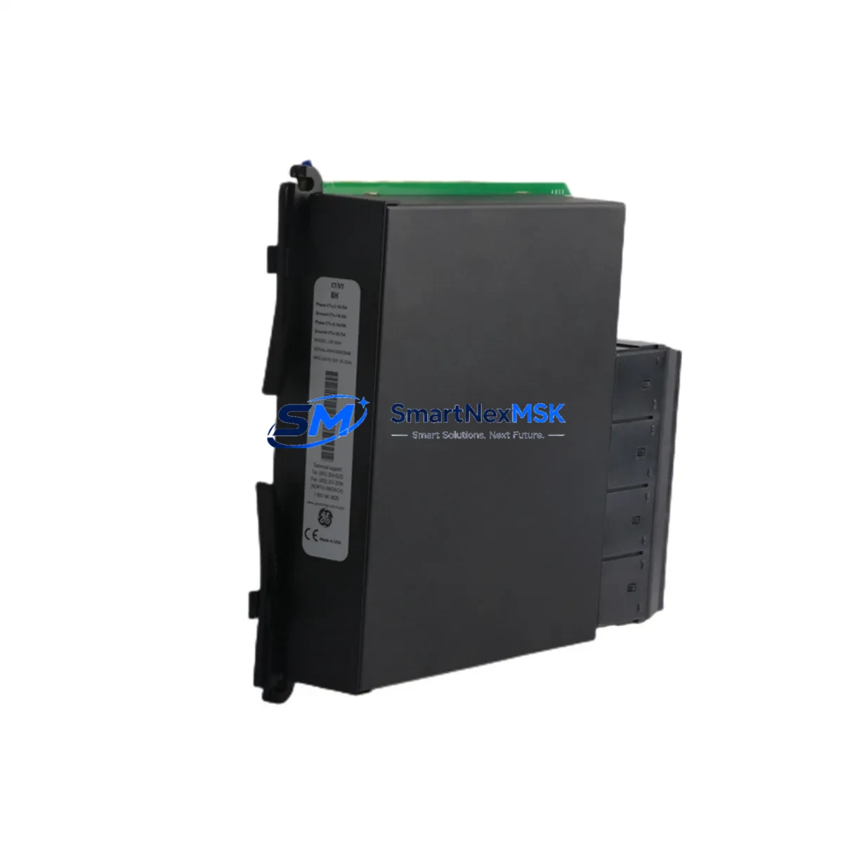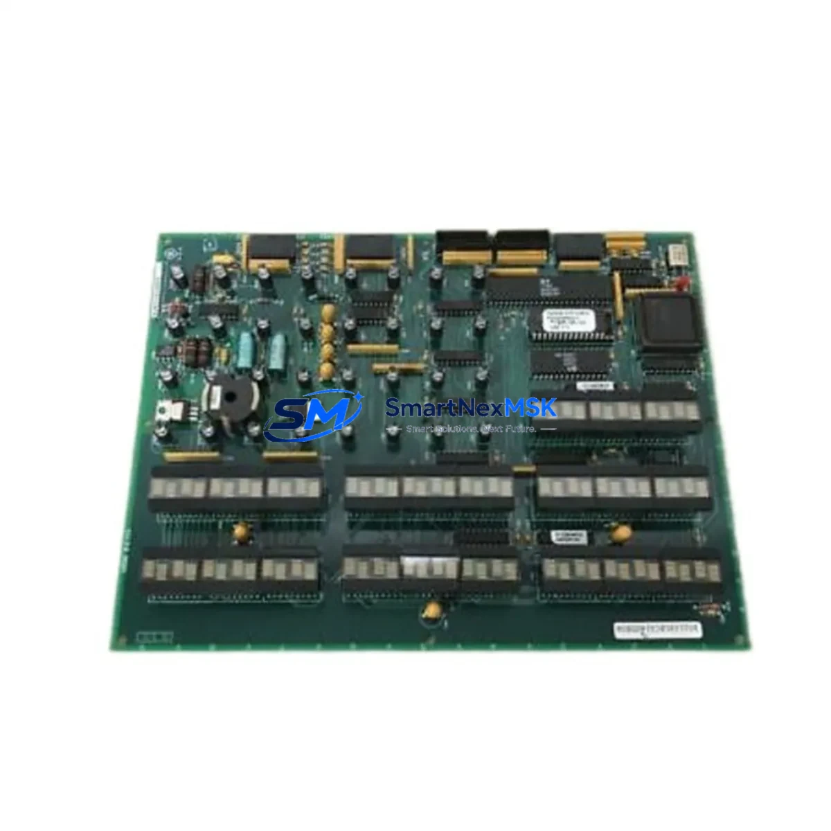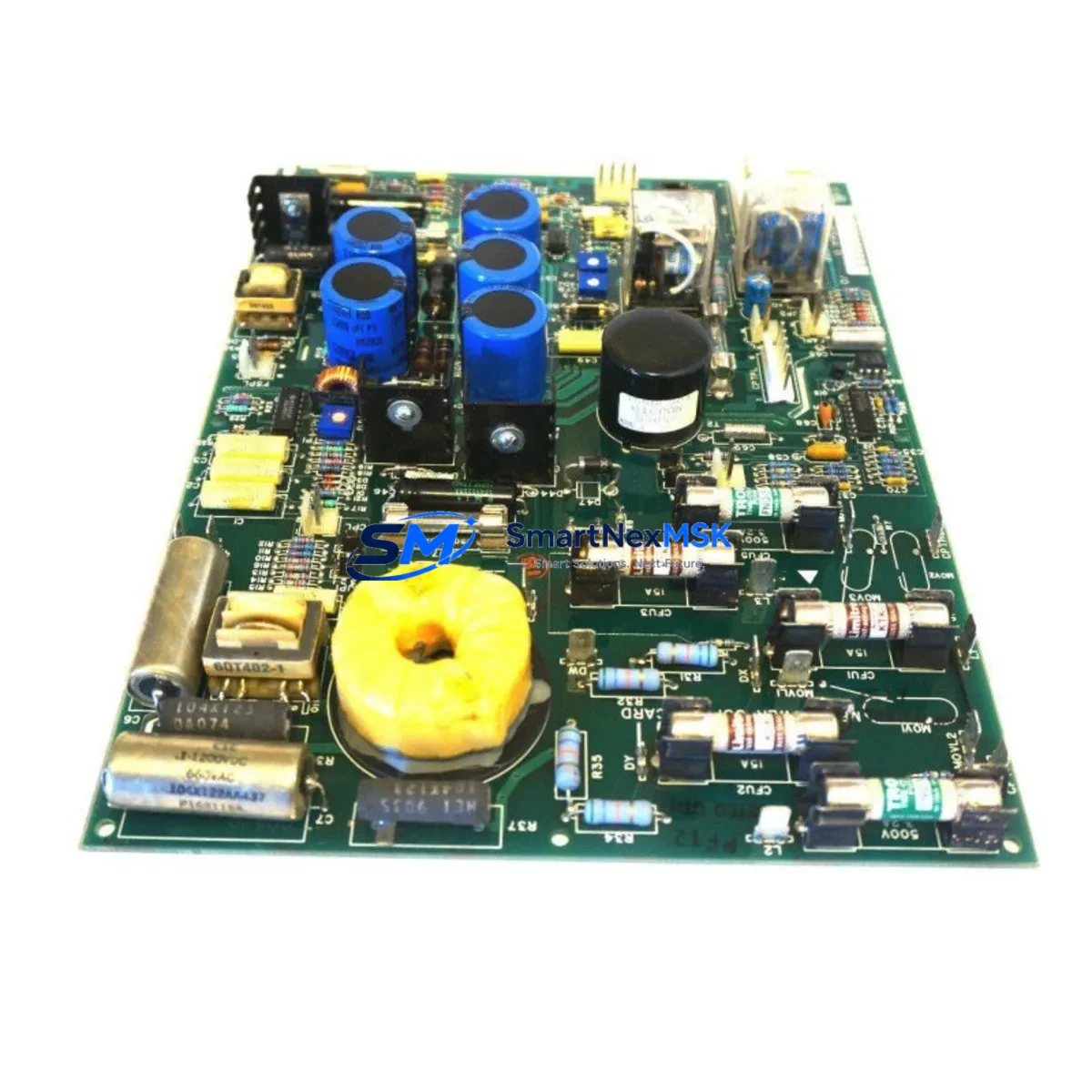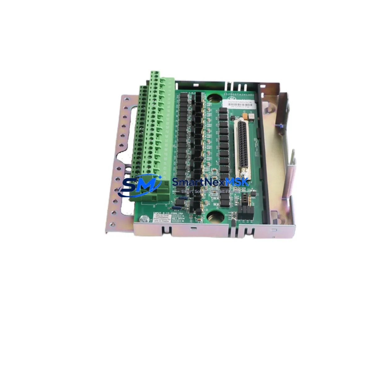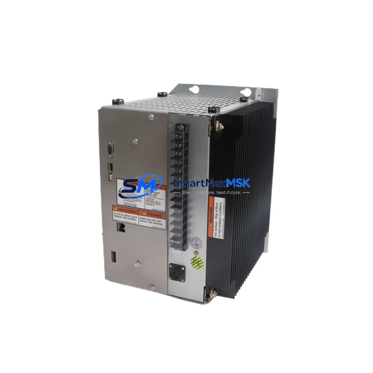
GE 151X1235DB15SA01 Retrofit-Ready Excitation Control for EX2100e Control Systems
The GE 151X1235DB15SA01 is a retrofit-ready excitation control module engineered for seamless integration into GE EX2100e static excitation systems. As legacy excitation platforms approach end-of-life and OEM spare parts become increasingly scarce, this module provides a verified, wiring-compatible replacement that preserves existing control logic, terminal assignments, and communication architecture — minimizing engineering rework and unplanned downtime during generator excitation system upgrades.
Designed for power generation facilities, industrial plants, and utilities operating aging GE EX2100 or EX2100e excitation controllers, the 151X1235DB15SA01 addresses the most critical pain points in excitation system modernization: terminal compatibility, backplane interface alignment, ARCNET communication continuity, and AVR (Automatic Voltage Regulator) program retention. Whether you are replacing a failed board, upgrading a degraded excitation cabinet, or executing a planned outage retrofit, this module is pre-tested and ready for field installation.
Upgrade Compatibility Table
| Parameter | Details |
|---|---|
| SKU / Part Number | 151X1235DB15SA01 |
| Compatible Platform | GE EX2100e Static Excitation System |
| Also Replaces | GE EX2100, EX2000 excitation control boards (verify backplane revision) |
| Module Function | Excitation Control — AVR regulation, field current control, PSS interface |
| Communication Protocol | ARCNET (peer-to-peer, deterministic) |
| Backplane Interface | EX2100e standard VME-style backplane; verify slot address before installation |
| Terminal / Wiring | Direct terminal-for-terminal replacement; no rewiring required for standard EX2100e cabinets |
| Power Supply Compatibility | 24 VDC logic supply; confirm cabinet PSU capacity before hot-swap |
| Installation Requirement | Module address configuration via DIP switch or software; match original slot assignment |
| Program Compatibility | Retains existing AVR tuning parameters; re-download from ToolboxST or Mark VIe Toolbox recommended post-swap |
| Commissioning Note | Verify HMI faceplate tag mapping and alarm setpoints after replacement |
| Warranty | 12-Month Warranty — covers manufacturing defects and functional failure under normal operating conditions |
| Lead Time | Ships within 1–3 business days from verified stock |
| Condition | New / Surplus New / Tested Refurbished (specify at order) |
Retrofit Planning for Existing Automation Systems
A successful EX2100e excitation system retrofit begins well before the maintenance window opens. Engineers must audit the existing cabinet layout, confirm the backplane revision, and document all terminal wiring assignments against the original GE engineering drawings. The 151X1235DB15SA01 slots directly into the EX2100e control rack, but pre-installation verification is essential to avoid configuration drift.
Start by confirming the 24 VDC power supply module within the excitation cabinet can sustain the inrush current during module initialization. In older EX2100 installations, the PSU may be operating near rated capacity — particularly if additional I/O expansion boards or communication modules have been added over time. If the cabinet includes a GE IS200ESELH1A Ethernet communication module or an IS200AEPAH1A analog I/O board, verify that the ARCNET network topology remains intact after the swap, as node address conflicts can cause the excitation controller to fault on startup.
For sites running a GE Mark VIe turbine control system in parallel with the EX2100e excitation platform, the retrofit scope expands to include cross-system signal verification. The IS200TRLYH1A relay output module and IS200VTURH1A turbine control board may share hardwired interlock signals with the excitation system — these must be traced and confirmed before the outage begins. Similarly, if the plant uses a GE ToolboxST engineering workstation for configuration management, ensure the software version is compatible with the replacement module’s firmware baseline.
Terminal block wiring on the EX2100e is standardized, but field modifications made during previous maintenance cycles can introduce undocumented deviations. Photograph all terminal connections before removal. Pay particular attention to the field current feedback circuit, the PT (potential transformer) input terminals, and the CT (current transformer) secondary connections — incorrect reassignment of these signals will cause AVR instability or protection relay misoperation. If the cabinet includes a GE IS200PSYCH1A power supply board, inspect its output voltage under load before and after the module swap to confirm stability.
For plants migrating from older GE EX2000 excitation platforms to EX2100e architecture, the 151X1235DB15SA01 serves as a key bridging component. The EX2000-to-EX2100e migration path typically involves replacing the legacy DS200SDCCG1A control card and associated I/O boards with the EX2100e module set, while retaining the existing excitation transformer, field breaker, and power bridge. This approach reduces capital expenditure and allows the plant to leverage existing cabinet infrastructure while gaining access to modern diagnostics, improved AVR algorithms, and enhanced communication capabilities.
HMI integration is another critical retrofit checkpoint. If the plant operates a GE Cimplicity HMI or a third-party SCADA system connected via Modbus TCP or OPC-DA, verify that the excitation system’s data tags — field voltage, field current, reactive power output, and excitation status — are correctly mapped after the module replacement. Tag name changes or address shifts introduced by the new module firmware can cause blank or frozen displays on the operator workstation, which must be resolved before returning the unit to service.
Downtime Control During System Migration
Minimizing outage duration during an excitation module replacement requires a structured pre-outage preparation protocol. Before the generator is taken offline, download and archive the complete AVR configuration from the existing 151X1235DB15SA01 or its predecessor using ToolboxST. Save the configuration file with a timestamped backup label and store it on both the engineering workstation and a removable drive kept in the control room.
During the outage window, follow a strict sequence: isolate the excitation cabinet from the generator field circuit, de-energize the 24 VDC logic supply, remove the failed or end-of-life module, install the replacement 151X1235DB15SA01, restore power, and perform a cold-start functional check before reconnecting the field circuit. This sequence protects the generator rotor winding from inadvertent energization during the swap and prevents damage to the new module from transient voltages present in the field circuit.
After installation, re-download the archived AVR configuration to the new module. Perform a no-load voltage build-up test to verify AVR response, then check the PSS (Power System Stabilizer) gain settings if the unit operates in parallel with the grid. Confirm that all protection relay setpoints — field overcurrent, loss of excitation, and underexcitation limiter — are correctly active before synchronizing the generator. A structured commissioning checklist, completed and signed by the responsible engineer, provides the audit trail required by most utility and industrial plant safety management systems.
For plants with tight outage windows, having a pre-tested spare 151X1235DB15SA01 on the shelf — verified against the plant’s specific firmware version and configuration file — is the single most effective strategy for reducing mean time to repair (MTTR). Our 12-month warranty covers the replacement module from the date of shipment, providing assurance that the spare inventory investment is protected.
Retrofit Support FAQ
Q1: Is the GE 151X1235DB15SA01 a direct drop-in replacement for the existing EX2100e excitation control board?
A: Yes, for standard EX2100e cabinet configurations, the 151X1235DB15SA01 is a terminal-for-terminal, slot-for-slot replacement. No rewiring is required in unmodified cabinets. However, sites with field modifications should verify terminal assignments against the original GE wiring diagrams before installation. Module slot address (DIP switch or software-configured) must match the original assignment to avoid ARCNET node conflicts.
Q2: Can I retain my existing AVR tuning parameters after replacing the module?
A: Yes. Archive the existing configuration using GE ToolboxST before the outage. After installing the 151X1235DB15SA01, re-download the saved configuration file. The module accepts the standard EX2100e configuration format. Post-download, perform a no-load voltage build-up test to confirm AVR response before returning the unit to service. If the original configuration file is unavailable, our technical team can assist with baseline parameter reconstruction based on the generator nameplate data.
Q3: What communication protocol does the 151X1235DB15SA01 use, and is it compatible with my existing network?
A: The module communicates via ARCNET, the deterministic peer-to-peer protocol standard across the GE EX2100e platform. It is fully compatible with existing EX2100e ARCNET networks. If your site is migrating from an older EX2000 platform that used a different communication architecture, a protocol bridge or network reconfiguration may be required — contact us with your system topology for a pre-sale compatibility assessment.
Q4: What does the 12-month warranty cover, and what is the return process if the module fails?
A: The 12-month warranty covers manufacturing defects and functional failure under normal operating conditions from the date of shipment. It does not cover damage caused by incorrect installation, overvoltage events, or physical mishandling. If a warranty claim is required, contact our sales team with the order number and a description of the failure mode. We will arrange return shipping and provide a replacement or repair within an agreed lead time. All modules are functionally tested before shipment to minimize the risk of DOA (dead-on-arrival) failures.
© 2026 SMARTNEXMSK. All rights reserved.
Original Source: https://smartnexmsk.com
Contact: [email protected] | +86 18259474341