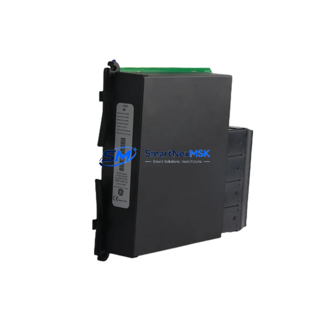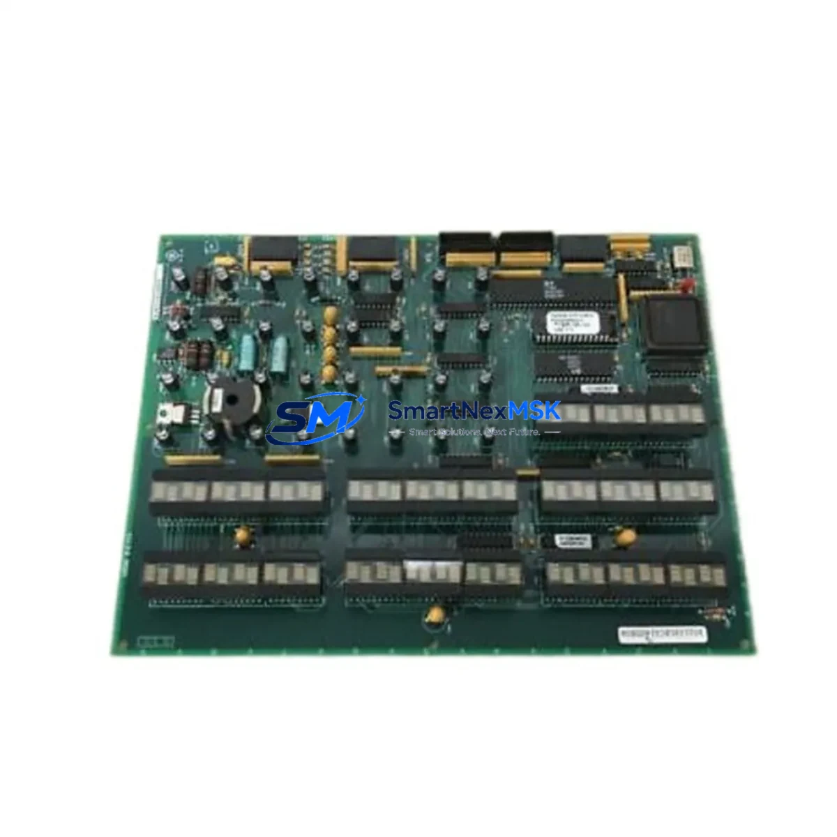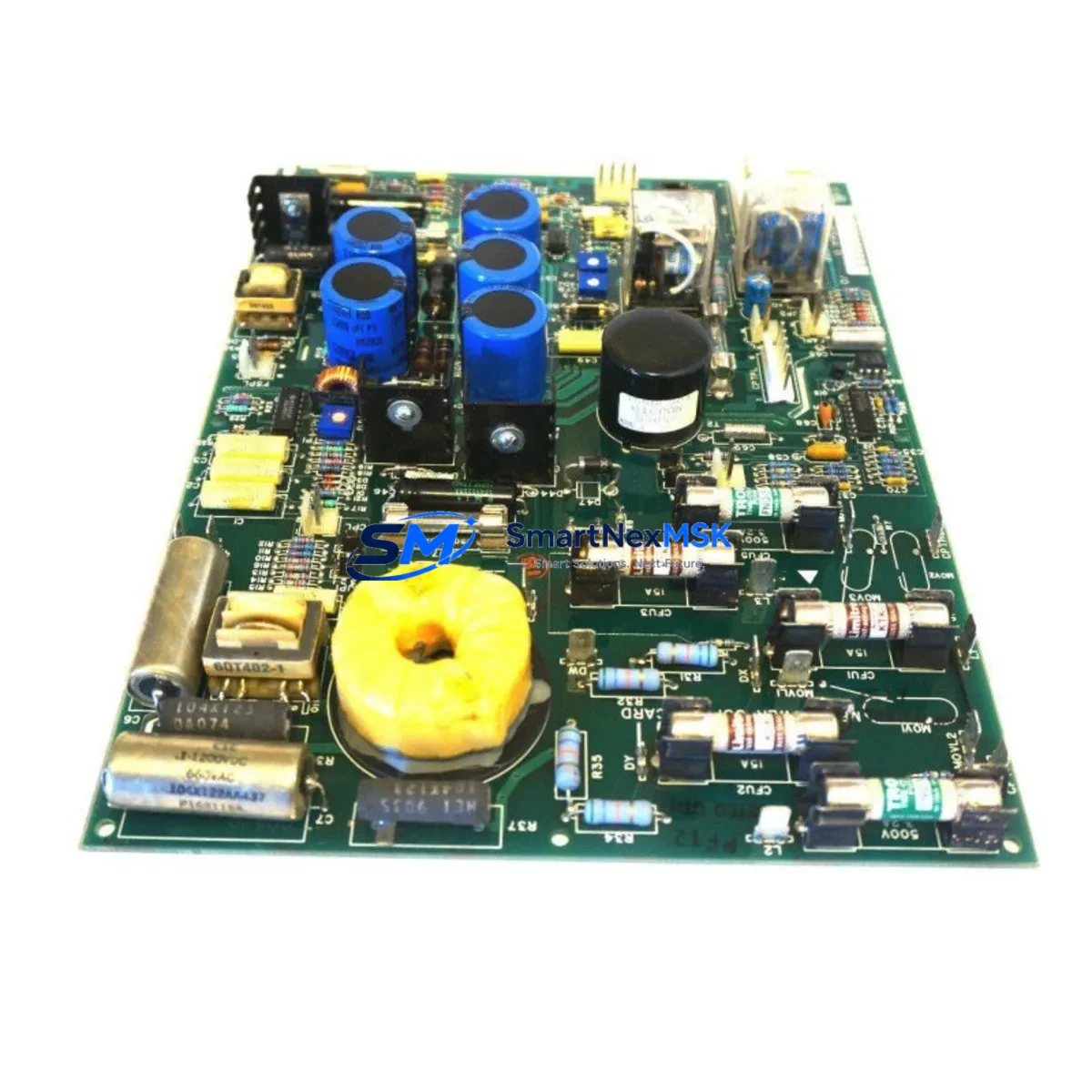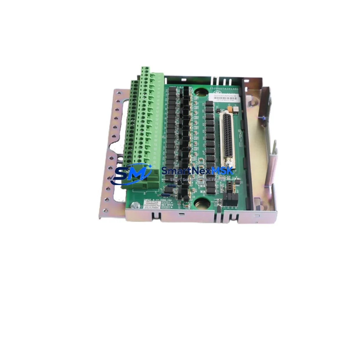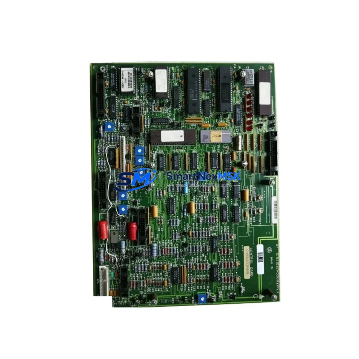
GE 531X300CCHAFM5 Maintenance-Ready Spare for Mark V Automation
The GE 531X300CCHAFM5 is an original spindle drive control board designed for GE Mark V turbine control systems. In industrial facilities where continuous operation is non-negotiable, unplanned downtime caused by a failed control board can cascade into hours of lost production. Stocking a verified, tested spare of the 531X300CCHAFM5 is a frontline strategy for maintenance engineers managing legacy GE Mark V panels, gas turbine control cabinets, and integrated drive systems.
This board governs spindle drive regulation within the Mark V architecture, interfacing directly with the I/O processor modules and power conditioning circuits that sustain turbine speed control. When this component degrades — through thermal cycling, capacitor aging, or signal path contamination — the symptoms often appear first as erratic speed references, nuisance trips, or communication faults on the Mark V operator interface. Early identification and rapid board swap are critical to restoring system stability before a full shutdown is required.
Each unit supplied by SMARTNEXMSK is sourced from verified industrial channels, functionally tested prior to dispatch, and backed by a 12-month warranty. Fast international shipping ensures that your maintenance team receives the part within the shortest possible lead time, minimizing exposure to extended downtime.
Spare Maintenance Table
| Part Number | 531X300CCHAFM5 |
| Brand | General Electric (GE) |
| Series | Mark V Turbine Control System |
| Product Type | Spindle Drive Control Board |
| Form Factor | PCB Module, rack-mount compatible |
| Compatibility | GE Mark V (TMR & Simplex configurations), Mark V LM, legacy Mark IV upgrade paths |
| Typical Application | Gas turbine spindle drive regulation, speed reference control, drive interface |
| Operating Environment | Industrial control cabinet; ambient 0–55 °C, humidity ≤ 95% non-condensing |
| Installation | Direct board replacement; observe ESD precautions; verify backplane connector alignment |
| Maintenance Recommendation | Inspect annually; replace on first sign of thermal discoloration, capacitor bulge, or communication fault |
| Origin | USA |
| Warranty | 12 Months |
| Pre-shipment Testing | Functional test performed on every unit before dispatch |
Maintenance Planning for Continuous Operation
Replacing the 531X300CCHAFM5 in a live Mark V system is rarely an isolated task. Experienced maintenance engineers know that a spindle drive board failure is often accompanied by — or caused by — degradation in adjacent components. During any planned or emergency replacement of this board, the following components should be inspected or tested concurrently to prevent repeat failures and ensure full system restoration:
- GE Mark V Power Supply Module (PSCA / PSCB) — Verify output voltage rails are within tolerance. An under-voltage condition on the 5 VDC or 24 VDC bus is a common root cause of control board failure.
- I/O Processor Board (IONET / IOHA) — Check for communication errors on the IONet bus. A degraded I/O processor can generate false fault signals that mimic spindle drive board failure.
- Mark V Relay Output Module — Inspect relay contacts for pitting or welding, particularly on trip and permissive circuits tied to the spindle drive loop.
- Terminal Boards (TBCI / TBQC) — Inspect screw terminals for loose connections, corrosion, or thermal damage. Poor terminal contact is a leading cause of intermittent drive faults.
- Signal Isolators (4–20 mA loop isolators) — Verify that analog speed reference signals entering the spindle drive circuit are clean and within range. Ground loops introduced through degraded isolators can corrupt drive commands.
- Fuse and Circuit Protection (control cabinet fuse blocks) — Replace any fuses that show signs of thermal stress. A blown or weakened fuse on the drive power feed is often overlooked during emergency repairs.
- HMI / Operator Interface Panel — After board replacement, confirm that the Mark V operator interface correctly displays speed feedback and drive status. A configuration mismatch can prevent the new board from being recognized.
- Backplane / Rack Connector — Clean and inspect the backplane connector pins for oxidation. Poor backplane contact is a silent failure mode that can cause a new board to underperform.
- Battery-Backed Memory Module — Verify that system configuration and calibration data stored in the Mark V memory module is intact after the board swap, particularly if the system was fully de-energized during maintenance.
- Isolate and document: Record the current fault codes displayed on the Mark V operator interface. Photograph the board position, wiring, and connector orientation before removal.
- De-energize safely: Follow your site’s lockout/tagout (LOTO) procedure for the control cabinet. Discharge any residual voltage on the drive bus before handling the board.
- Remove the failed board: Release the board retaining clips, disconnect the backplane connector, and extract the 531X300CCHAFM5. Inspect the backplane connector for damage before installing the replacement.
- Install the replacement: Handle the new board with ESD protection. Seat it firmly into the backplane, ensuring all connector pins are fully engaged. Secure the retaining clips.
- Re-energize and verify: Power up the control cabinet in sequence. Monitor the Mark V operator interface for fault-free startup. Confirm that spindle speed reference and feedback signals are within expected parameters.
- Functional test: Run the turbine through a controlled start sequence to verify that the spindle drive responds correctly to speed commands. Log the results for your maintenance records.
- Update spare parts inventory: Record the replacement in your CMMS and initiate a reorder for the consumed spare to maintain your buffer stock level.
Maintaining a small, curated spare parts inventory covering these components — alongside the 531X300CCHAFM5 — is the most effective strategy for reducing mean time to repair (MTTR) in Mark V-controlled turbine installations.
Site Replacement Workflow
When the 531X300CCHAFM5 is identified as the failed component, follow this structured replacement workflow to minimize downtime and ensure system compatibility:
This workflow applies equally to planned maintenance windows and emergency breakdown scenarios. The key difference is preparation: a pre-staged, tested spare of the 531X300CCHAFM5 reduces the replacement cycle from days to hours.
Spare Parts Support FAQ
Q1: Is the 531X300CCHAFM5 compatible with both TMR and Simplex Mark V configurations?
A: Yes. The 531X300CCHAFM5 spindle drive control board is designed for use within the GE Mark V platform, which supports both Triple Modular Redundant (TMR) and Simplex architectures. Always verify the slot assignment and system configuration file before installation to confirm the board is recognized correctly by the Mark V controller.
Q2: What testing is performed before shipment?
A: Every 531X300CCHAFM5 unit supplied by SMARTNEXMSK undergoes functional testing prior to dispatch. This includes power-on verification, signal path continuity checks, and visual inspection for component-level defects. A test report is available upon request for critical maintenance applications.
Q3: How should this spare be stored if not immediately installed?
A: Store the board in its original ESD-protective packaging in a dry, temperature-controlled environment (10–40 °C, humidity ≤ 60% non-condensing). Avoid stacking heavy items on the package. Inspect the board annually if held in long-term storage, and replace the ESD bag if it shows signs of degradation.
Q4: What does the 12-month warranty cover?
A: The 12-month warranty covers manufacturing defects and functional failures under normal operating conditions. It does not cover damage caused by incorrect installation, overvoltage events, physical impact, or unauthorized modification. In the event of a warranty claim, contact SMARTNEXMSK with the order reference and a description of the fault. Replacement or repair will be arranged promptly to minimize your downtime exposure.
© 2026 SMARTNEXMSK. All rights reserved.
Original Source: https://smartnexmsk.com
Contact: [email protected] | +86 18259474341