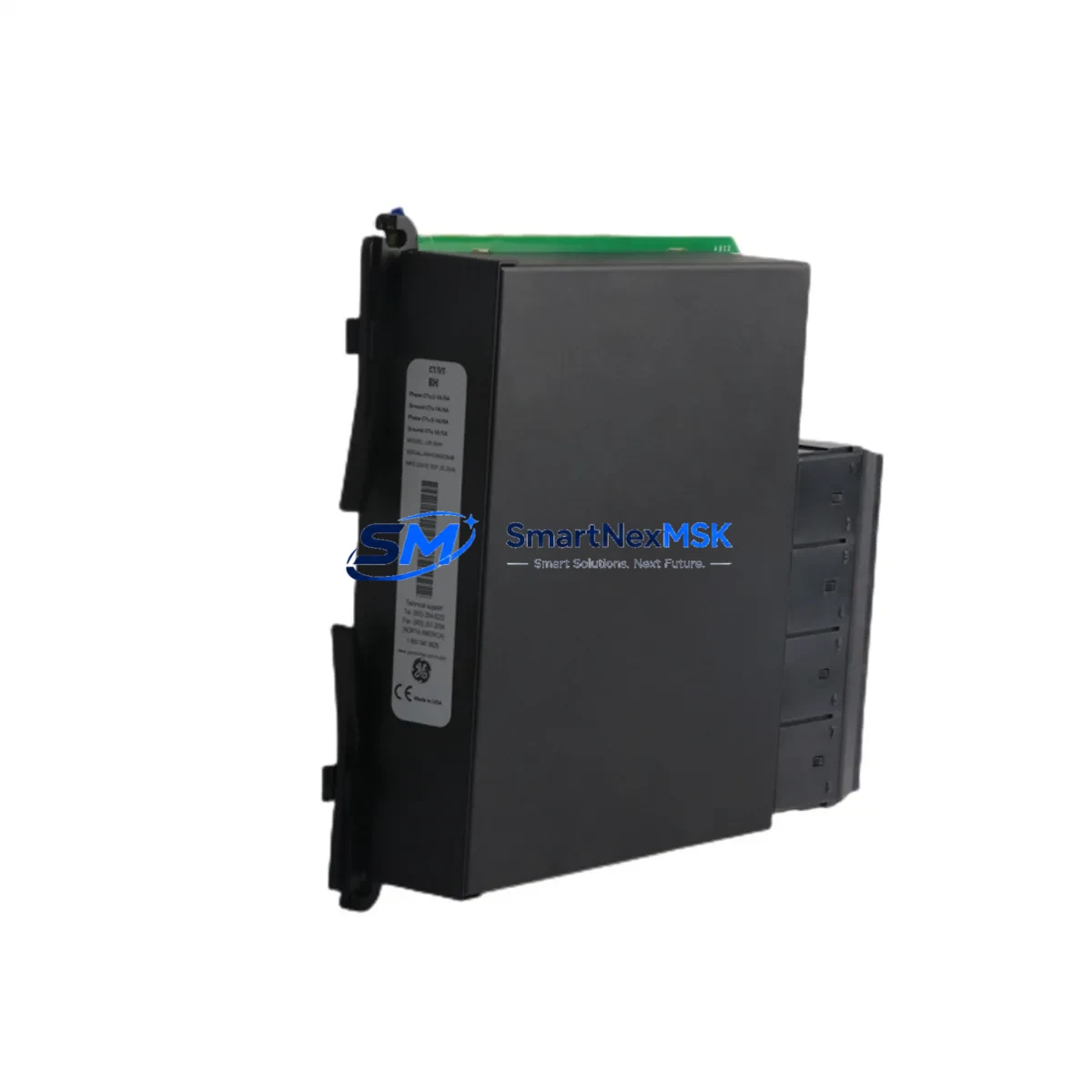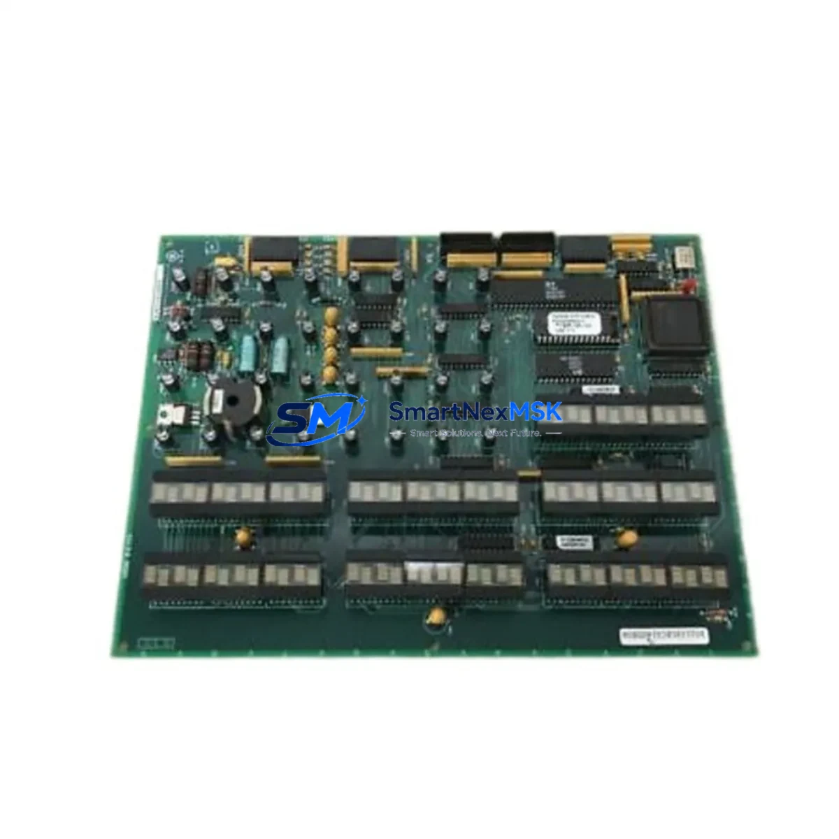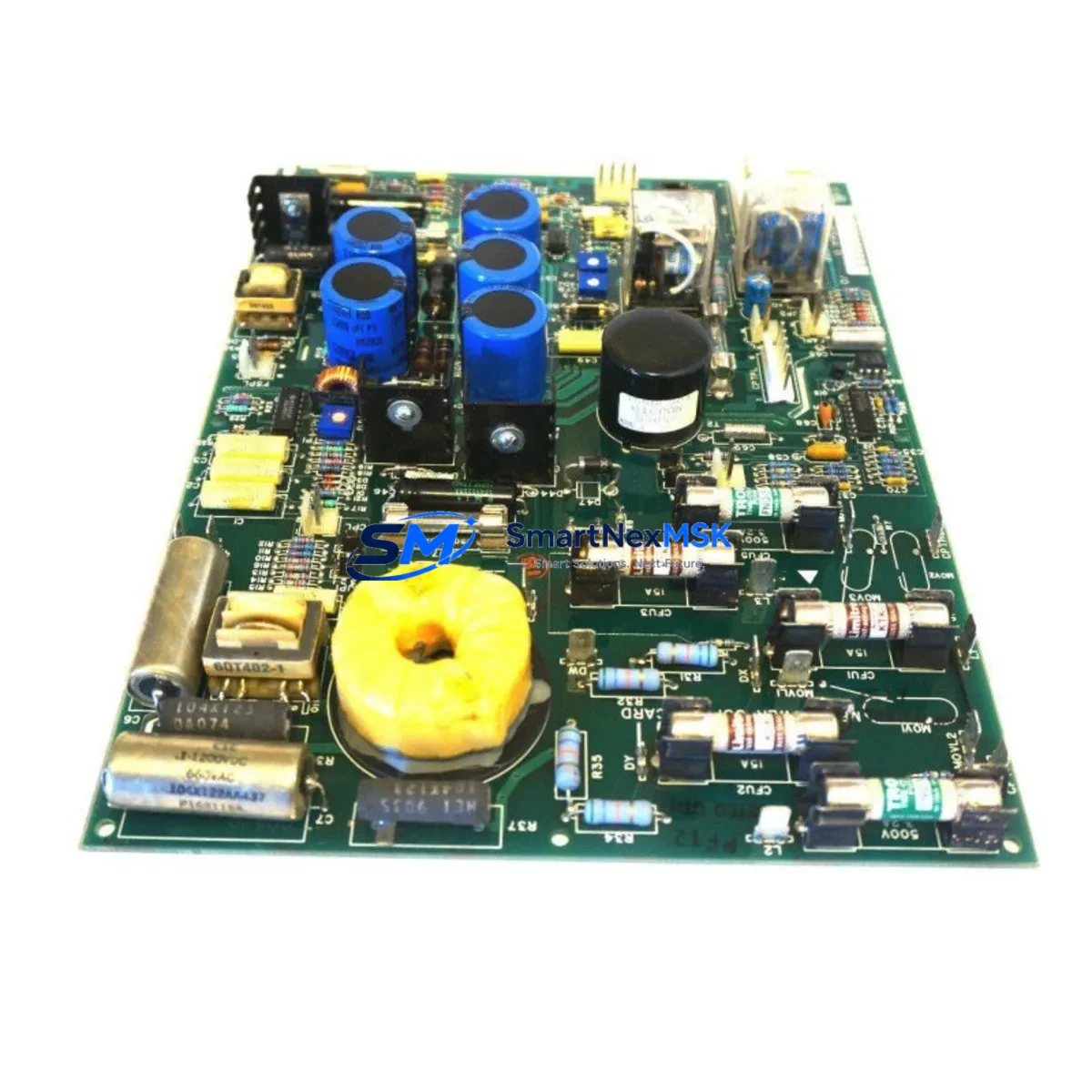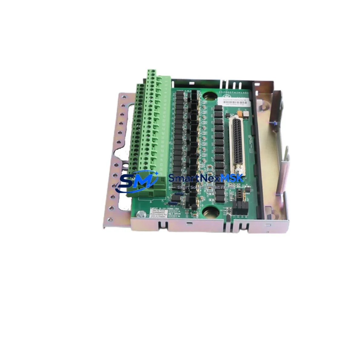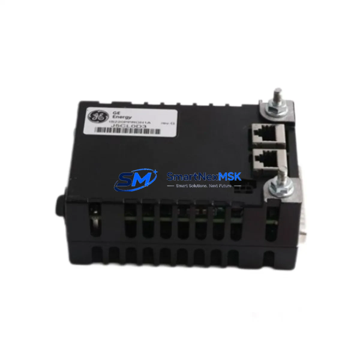
GE 531X300CCHBDM3 Maintenance-Ready Spare for 531X Automation
The GE 531X300CCHBDM3 is an original drive control PCB designed for General Electric’s 531X Series AC variable-speed drives, widely deployed across industrial automation systems in power generation, oil & gas, water treatment, and heavy manufacturing. When this board fails, the entire drive becomes inoperable — resulting in unplanned downtime that can cost thousands of dollars per hour. Sourcing a verified, tested replacement quickly is the single most effective way to restore production and protect your maintenance budget.
At SMARTNEXMSK, every 531X300CCHBDM3 unit is inspected, function-tested, and shipped with a 12-month warranty. We maintain dedicated stock of this board to support emergency replacement, planned overhaul cycles, and long-term spare parts inventory programs for facilities running legacy GE 531X drive systems.
Spare Maintenance Table
| Parameter | Specification / Detail |
|---|---|
| Part Number / SKU | 531X300CCHBDM3 |
| Brand | General Electric (GE) |
| Series | 531X Series AC Variable-Speed Drive |
| Board Function | Drive Control PCB — gate firing, feedback processing, fault logic |
| Compatible Drive Frames | GE 531X Series (multiple frame sizes); verify drive nameplate before installation |
| Input Voltage (Logic) | +5 VDC / ±15 VDC (supplied by drive power supply board) |
| Communication Interface | Internal backplane bus; compatible with 531X serial communication options |
| Mounting | Card-cage / backplane slot mount; standard 531X drive enclosure |
| Operating Temperature | 0°C to +55°C (drive enclosure ambient) |
| Product Condition | Original spare — new or refurbished-to-spec, fully tested |
| Warranty | 12 Months from date of shipment |
| Lead Time | In-stock: ships within 1–3 business days |
| Shipping | Worldwide; ESD-safe anti-static packaging |
| Application Environment | Industrial: power plants, pumping stations, compressor drives, conveyor systems |
| Maintenance Recommendation | Replace at first sign of fault codes, erratic speed control, or drive trip events |
Maintenance Planning for Continuous Operation
Replacing the 531X300CCHBDM3 control board is rarely an isolated task. Experienced maintenance engineers know that a control board failure in a 531X drive is often preceded or accompanied by stress on adjacent components. A thorough site replacement should include inspection of the following systems and components:
Begin with the 531X power supply board (such as the 531X301PCHBDG1 or equivalent), which provides regulated DC rails to the control PCB. A degraded power supply can cause repeated control board failures if not addressed simultaneously. Next, inspect the 531X gate driver board — if the control board has been subjected to a fault condition, gate firing signals may have caused stress on the IGBT driver circuitry.
Check all I/O terminal blocks and wiring harnesses within the drive enclosure. Loose or corroded connections on analog speed reference inputs, digital run/stop commands, and fault relay outputs are common contributors to intermittent control board faults. The 531X analog input/output board should be verified for signal integrity, particularly in applications with 4–20 mA process feedback loops.
For drives integrated into a DCS or PLC network, inspect the 531X serial communication board (Modbus RTU or DeviceNet variants) to confirm that communication parameters are intact after the board swap. In systems using a GE Mark V or Mark VI turbine control panel, verify that the drive’s network node address and baud rate settings are correctly restored post-replacement.
The drive’s main contactor and pre-charge circuit should also be tested — a welded contactor or failed pre-charge resistor can subject the new control board to inrush stress on first power-up. Similarly, inspect DC bus capacitors for bulging or elevated ESR, as capacitor degradation is a leading cause of drive control board overvoltage faults.
For facilities maintaining a comprehensive spare parts cabinet, consider stocking the 531X encoder feedback board alongside this control PCB, particularly in closed-loop vector applications where encoder signal loss triggers immediate drive trips. A replacement HMI operator panel or keypad compatible with the 531X Series is also recommended for sites where the local display is used for commissioning and fault diagnostics during the replacement procedure.
Finally, verify that all fuses on the control power circuit (typically 1A–5A glass or ceramic types mounted on the drive’s control terminal strip) are intact and within rating. A blown control fuse is often misdiagnosed as a control board failure, and replacing the board without checking fuses will result in a repeat fault on first power-up.
Site Replacement Workflow
Step 1 — Isolation & Lockout/Tagout: De-energize the drive, apply LOTO, and wait for DC bus voltage to discharge below 50 VDC before opening the enclosure. Use a calibrated multimeter to verify bus voltage at the DC bus terminals.
Step 2 — Document Current Configuration: Before removing the 531X300CCHBDM3, photograph or record all DIP switch settings, jumper positions, and any parameter values stored on the board. Some 531X control boards retain drive parameters in onboard EEPROM — confirm whether parameters need to be re-entered after replacement.
Step 3 — Board Removal: Disconnect all ribbon cables and connectors from the control PCB in sequence. Handle the board by its edges only; use an ESD wrist strap. Note the orientation of all connectors before removal.
Step 4 — Replacement Board Inspection: Inspect the new 531X300CCHBDM3 for shipping damage. Verify that DIP switch and jumper settings match the removed board’s documented configuration before installation.
Step 5 — Installation & Power-Up: Seat the board firmly in the card-cage slot, reconnect all cables, and restore control power only (not main power) for initial diagnostics. Confirm that the drive’s fault display shows no active faults before restoring main power.
Step 6 — Functional Test: Run the drive at low speed (10–15 Hz) under no-load conditions to verify speed reference tracking, fault relay operation, and communication link status before returning the drive to full production load.
This workflow minimizes total downtime to under two hours for a prepared maintenance team, compared to multi-day delays when waiting for emergency repair of the original board.
Spare Parts Support FAQ
Q: Is the 531X300CCHBDM3 still available as a new original part, or only as a refurbished spare?
A: GE’s 531X Series drives are a mature product line. SMARTNEXMSK supplies both new-old-stock (NOS) original boards and fully refurbished-to-specification units, each tested and shipped with a 12-month warranty. Availability of new vs. refurbished stock is confirmed at time of order.
Q: How do I verify compatibility before ordering?
A: Provide your drive’s full nameplate data (model number, frame size, firmware revision, and the part number printed on the existing control board). Our technical team will cross-reference your drive’s bill of materials to confirm the correct board revision before shipment.
Q: What does the 12-month warranty cover?
A: The warranty covers manufacturing defects and functional failure under normal operating conditions for 12 months from the date of shipment. It does not cover damage caused by incorrect installation, overvoltage events, or failure of associated drive components (e.g., a failed power supply damaging the control board). Our team provides pre-shipment test documentation upon request.
Q: Can SMARTNEXMSK support long-term spare parts inventory programs for facilities with multiple 531X drives?
A: Yes. We offer reserved-stock agreements for facilities managing fleets of GE 531X drives, ensuring priority allocation of critical boards including the 531X300CCHBDM3, power supply boards, and gate driver assemblies. Contact our sales team to discuss volume pricing and consignment options.
© 2026 SMARTNEXMSK. All rights reserved.
Original Source: https://smartnexmsk.com
Contact: [email protected] | +86 18259474341