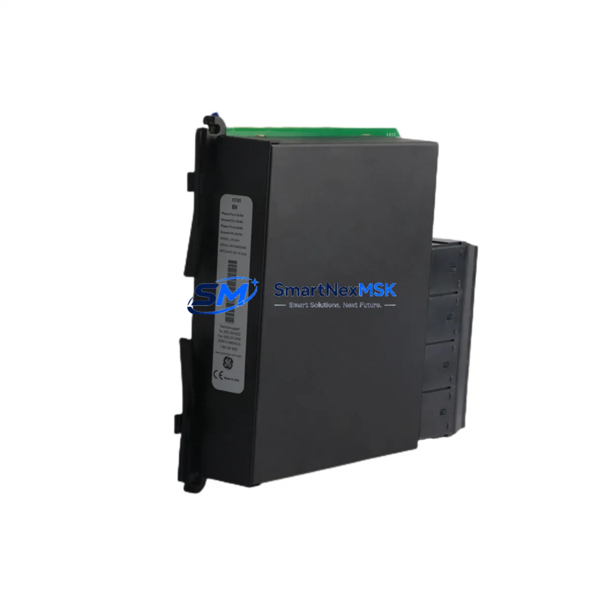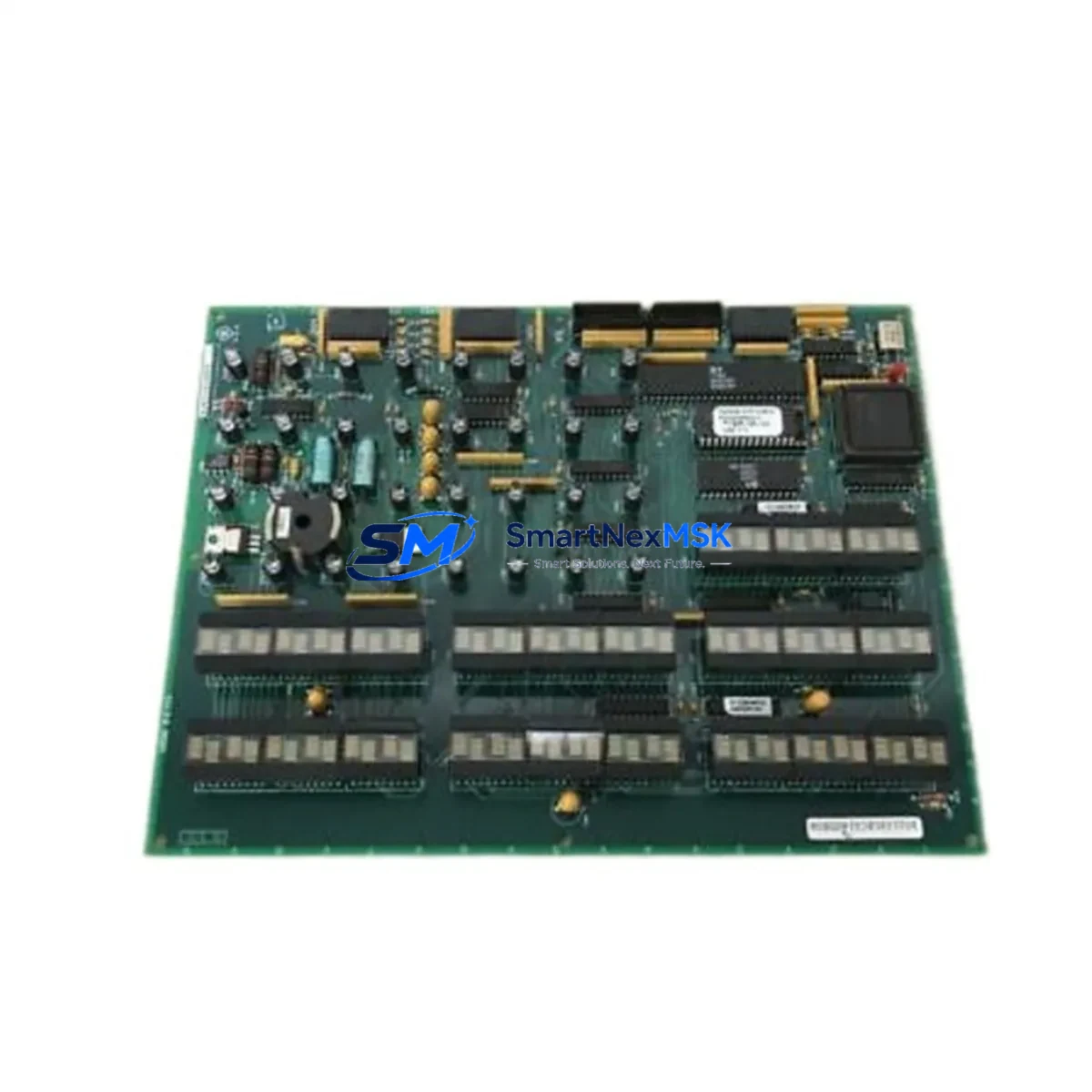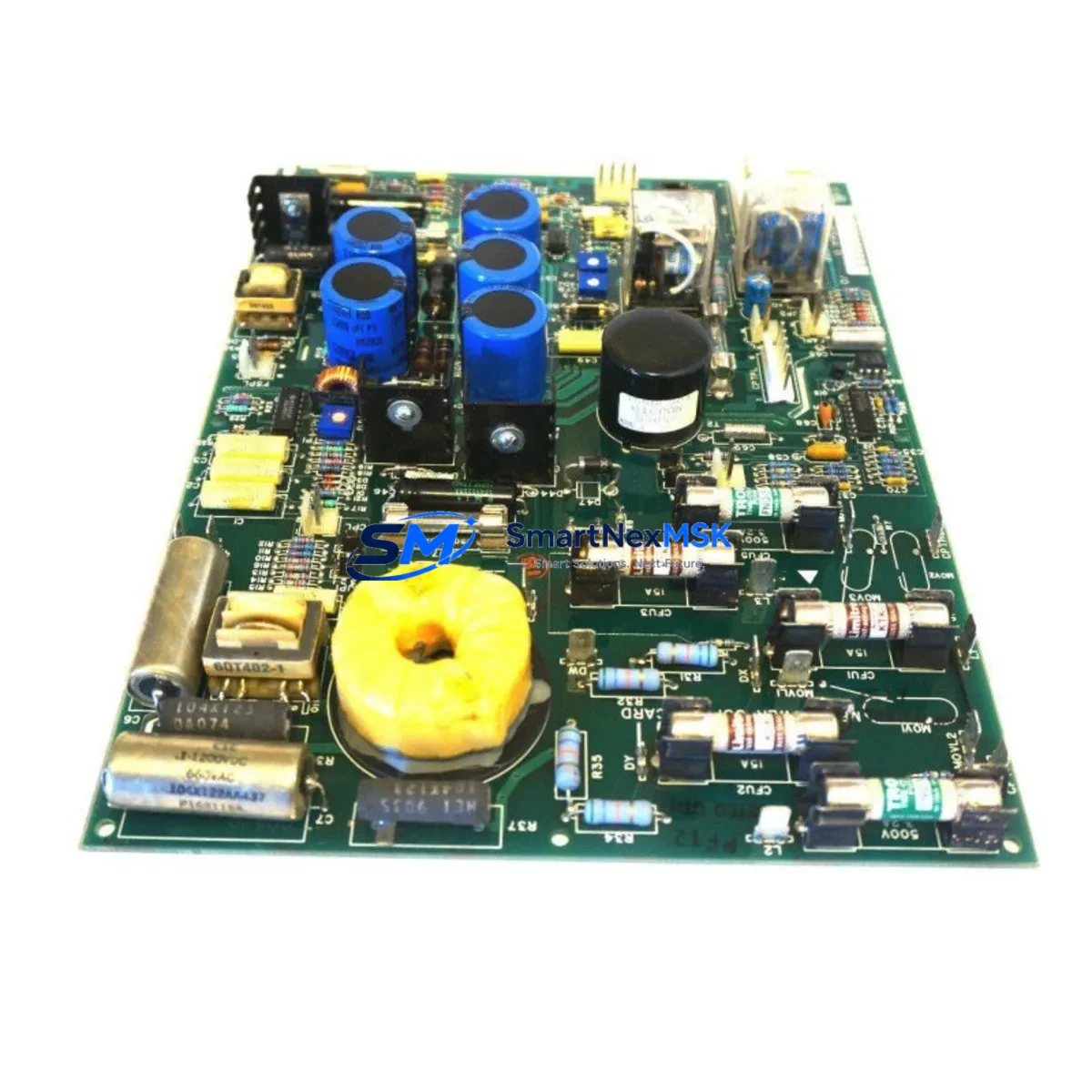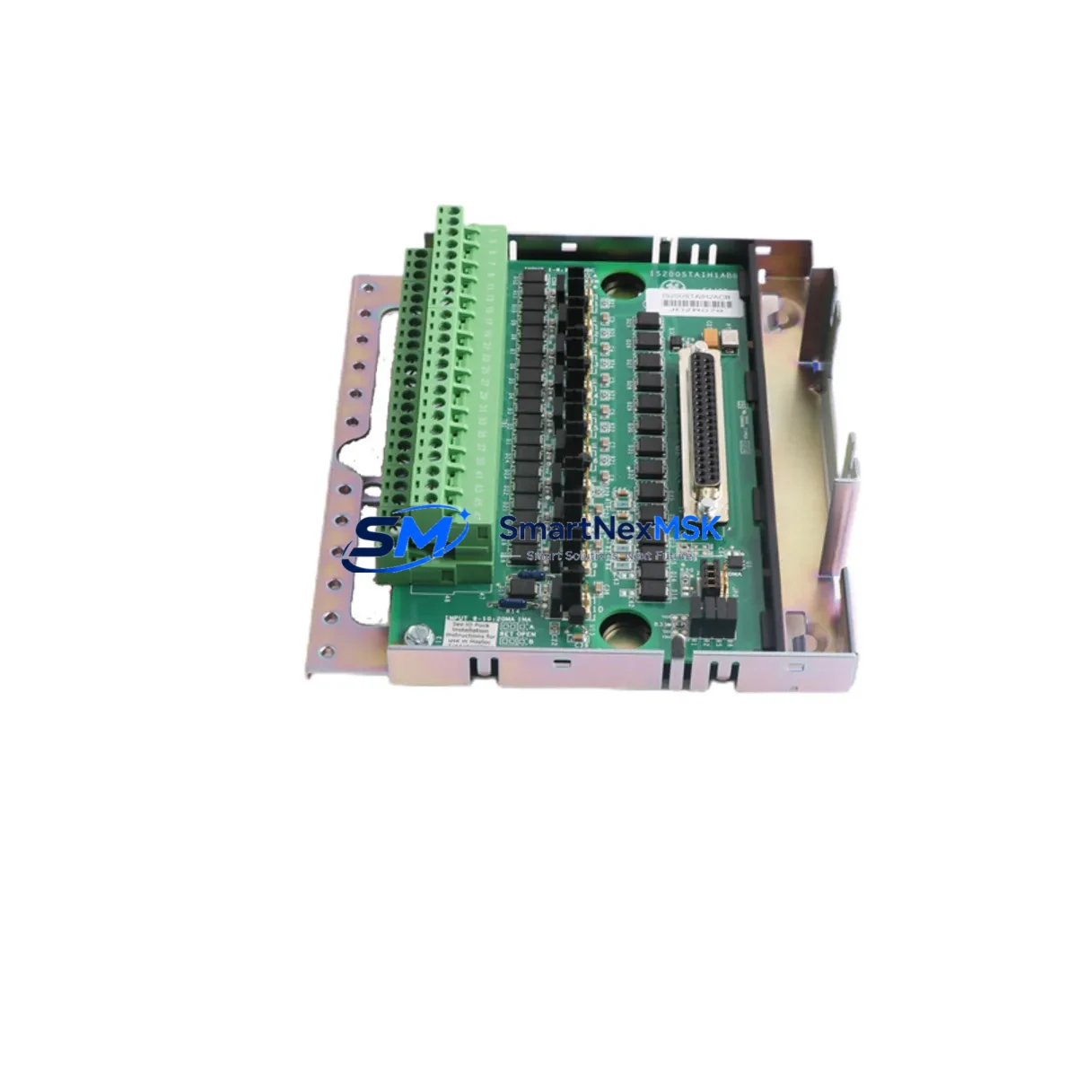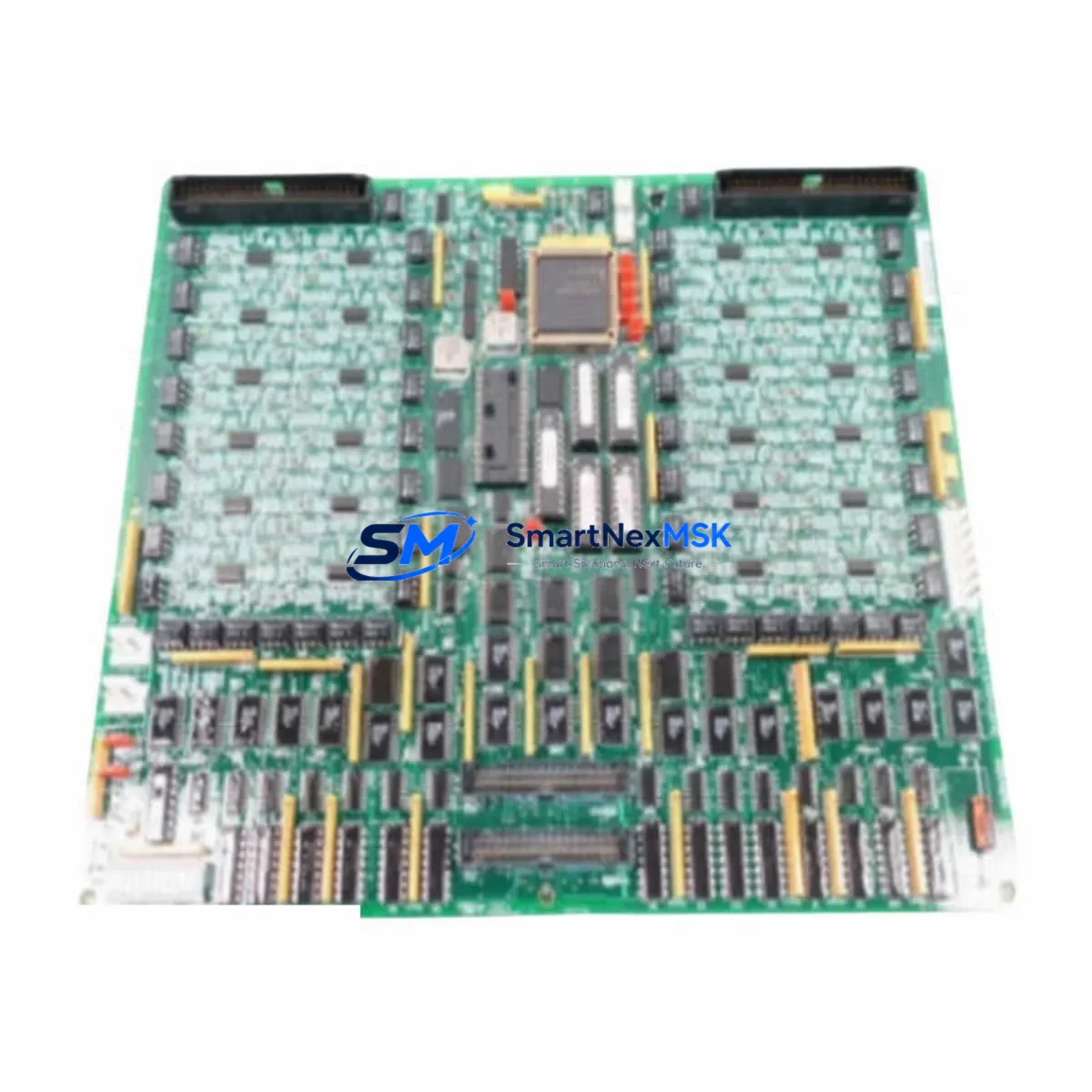
GE 531X301DCCRGG2 Retrofit-Ready Drive Control Board for Series Six & Mark V Control Systems
The GE 531X301DCCRGG2 is a retrofit-ready drive control board engineered for seamless integration into aging GE Series Six and Mark V control architectures. As legacy automation systems approach end-of-life and OEM support windows close, plant engineers and system integrators increasingly rely on verified replacement modules like the 531X301DCCRGG2 to extend operational continuity without committing to full platform migrations. This board serves as a direct functional replacement for discontinued drive control assemblies, supporting brownfield upgrade projects across power generation, oil & gas, petrochemical, and heavy manufacturing environments.
Each unit supplied by SMARTNEXMSK undergoes pre-shipment functional verification, including power-on self-test, I/O channel continuity checks, and communication link validation. All units are backed by a 12-month warranty covering manufacturing defects and functional failures under normal operating conditions. In-stock inventory ensures rapid dispatch, minimizing procurement lead times for time-critical maintenance and unplanned outage scenarios.
Upgrade Compatibility Table
| Parameter | Details |
|---|---|
| Compatible Platform | GE Series Six, Mark V Drive Control Systems |
| Module Function | Drive Control Board — analog/digital I/O interface, drive sequencing, feedback processing |
| Backplane Interface | Standard GE Series Six rack backplane; verify slot addressing before installation |
| Communication Protocol | Compatible with GE proprietary serial bus; verify baud rate and node address settings |
| Power Supply Requirement | Confirm rack PSU capacity (typically +5 VDC / ±15 VDC); validate against existing 531X305NTBAPG2 or equivalent power supply module |
| Terminal Wiring | Field wiring connects via terminal board; confirm TB compatibility with existing 531X307LTBAPG1 or equivalent terminal assembly |
| Replacement Scope | Direct drop-in for discontinued 531X301DCCRGG2 variants; verify firmware revision compatibility |
| Installation Requirement | No hardware modification required for standard slot replacement; module address DIP switch configuration may be required |
| Commissioning Note | Validate HMI screen tag mapping and alarm setpoints post-installation; re-download application logic if firmware mismatch detected |
| Warranty | 12 months from date of shipment — covers manufacturing defects and functional failures under normal operating conditions |
Retrofit Planning for Existing Automation Systems
Successful integration of the 531X301DCCRGG2 into an existing control system requires a structured pre-installation assessment. Begin by auditing the rack configuration: confirm the target slot is compatible with the Series Six backplane and that the adjacent modules — including the 531X305NTBAPG2 power supply module and any installed 531X309LTBAPG1 analog input boards — are functioning within specification. Overloaded or degraded power supply modules are a common root cause of premature drive control board failures and must be evaluated before replacement.
Terminal board compatibility is the next critical checkpoint. The 531X301DCCRGG2 interfaces with the field wiring through a dedicated terminal assembly. If the existing 531X307LTBAPG1 terminal board shows signs of corrosion, loose terminations, or insulation degradation, it should be replaced concurrently to avoid introducing new fault conditions. Label and photograph all field wiring before disconnection to ensure accurate re-termination.
For systems running GE’s proprietary communication bus, verify that the node address and baud rate settings on the replacement board match the original configuration. In multi-drop architectures where the 531X301DCCRGG2 communicates with a Mark V TCCA controller card or a TCCB turbine control core board, address conflicts will cause communication faults that may not be immediately obvious during initial power-up. Use the GE Toolbox or equivalent programming software to confirm the communication map before energizing the system.
I/O channel mapping must be validated against the existing application program. If the control logic was developed on a GE Series Six CPU module such as the IC600CPU772 or IC600CPU774, confirm that the drive control board’s analog and digital I/O assignments align with the program’s variable declarations. Mismatched I/O addressing is a frequent source of post-replacement commissioning delays. Where program modifications are required, ensure a backup of the original logic is preserved on a GE Series Six programming cable or equivalent offline storage before any edits are made.
HMI screen validation is often overlooked in retrofit projects. After the 531X301DCCRGG2 is installed and communication is confirmed, verify that all associated HMI faceplates — whether running on a legacy GE Cimplicity workstation or a modern SCADA platform — correctly reflect drive status, speed feedback, fault codes, and control mode. Tag name changes or address remapping introduced during the replacement process can silently break HMI displays without generating controller-level alarms.
Finally, for systems that include 531X311LTBAPG1 relay output boards or 531X313LTBAPG1 digital input assemblies in the same control cabinet, confirm that the replacement board’s installation does not disturb the rack grounding scheme or introduce ground loops through the terminal board wiring. A clean ground reference is essential for stable analog signal processing in drive control applications.
Downtime Control During System Migration
Minimizing unplanned downtime is the primary operational concern when replacing a drive control board in a live production environment. The recommended approach is to pre-stage the replacement 531X301DCCRGG2 with all DIP switch settings, firmware verification, and bench-level I/O testing completed before the maintenance window opens. This eliminates configuration discovery time during the outage and reduces the risk of extending the shutdown due to unexpected setup requirements.
Where the process permits, a controlled shutdown sequence should be executed to bring the drive to a safe stop state before de-energizing the control rack. Abrupt power loss to a running drive system can corrupt volatile memory in adjacent modules and may trigger protective relay operations that complicate restart procedures. Coordinate with the operations team to confirm that all interlocks are satisfied and that the process is in a stable hold condition before proceeding.
Preserve the original application program by uploading it from the controller to an offline backup immediately before the board swap. Even if no program changes are anticipated, having a verified backup eliminates recovery risk if the replacement board requires a fresh download. For Series Six systems, the upload procedure is performed via the programming port using GE’s Series Six programming software; for Mark V systems, the equivalent procedure uses the Mark V toolbox connected through the JPDM data manager card or the TCDA communication adapter.
After installation, follow a structured power-up sequence: energize the rack, confirm the module’s status LEDs indicate normal operation, verify communication link establishment, and perform a controlled I/O check before releasing the drive to automatic control. Document the as-found and as-left conditions for the maintenance record, including module serial numbers, firmware revisions, and any configuration changes made during the replacement. This documentation supports future troubleshooting and demonstrates compliance with site maintenance management system requirements.
Retrofit Support FAQ
Q1: Is the 531X301DCCRGG2 a direct drop-in replacement for all Series Six drive control board variants?
The 531X301DCCRGG2 is functionally compatible with the standard Series Six drive control slot, but variant suffixes (e.g., DCCRGG1 vs. DCCRGG2) may indicate firmware or hardware revisions. Confirm the original board’s part number and revision level before ordering. SMARTNEXMSK’s technical team can assist with cross-reference verification prior to shipment.
Q2: What commissioning steps are required after installing the replacement board?
At minimum: verify module address DIP switch settings, confirm communication link status on the controller diagnostic display, perform a full I/O channel check against the application program, validate HMI tag mapping, and confirm drive ready status before returning to automatic control. For Mark V-integrated systems, also verify the TCCA/TCCB communication handshake is re-established.
Q3: How is field wiring re-terminated after the board swap?
Field wiring connects to the drive control board via the associated terminal board assembly, not directly to the module. The terminal board remains in place during the board swap, so field wiring does not need to be disturbed if the terminal board is in good condition. If the terminal board is replaced simultaneously, re-terminate wiring according to the original as-built drawings and verify continuity before energizing.
Q4: What does the 12-month warranty cover, and what is the claims process?
The 12-month warranty covers manufacturing defects and functional failures under normal operating conditions from the date of shipment. It does not cover damage resulting from incorrect installation, overvoltage events, or physical mishandling. To initiate a warranty claim, contact SMARTNEXMSK with the order reference, module serial number, and a description of the failure symptom. Replacement or repair will be arranged based on fault diagnosis.
© 2026 SMARTNEXMSK. All rights reserved.
Original Source: https://smartnexmsk.com
Contact: [email protected] | +86 18259474341