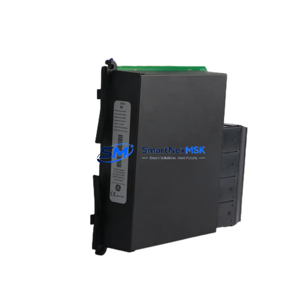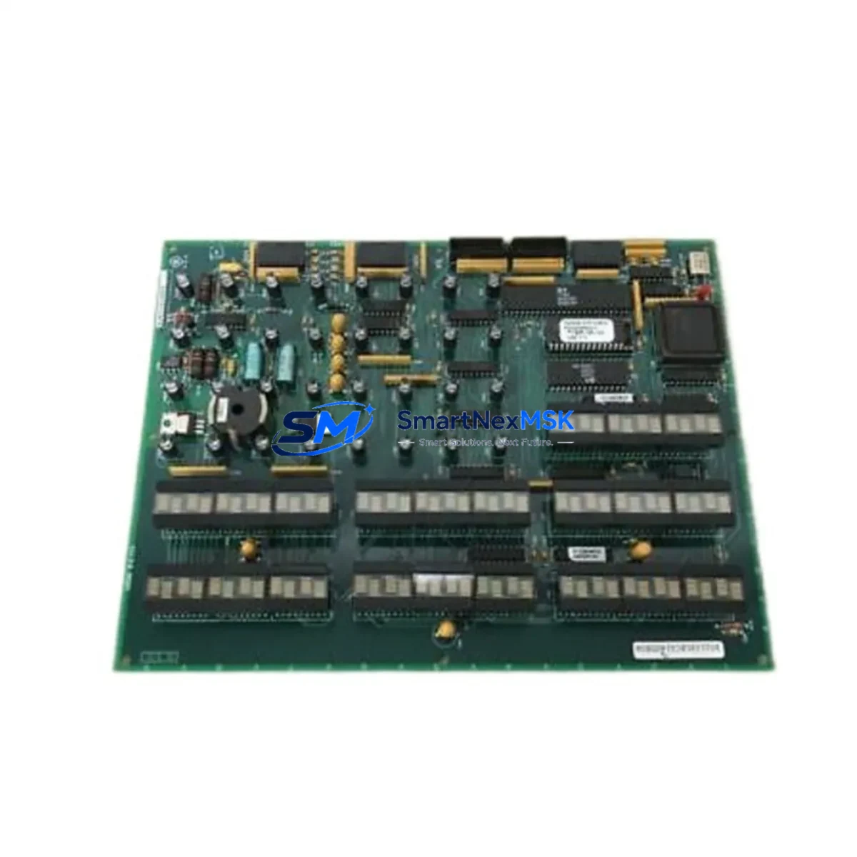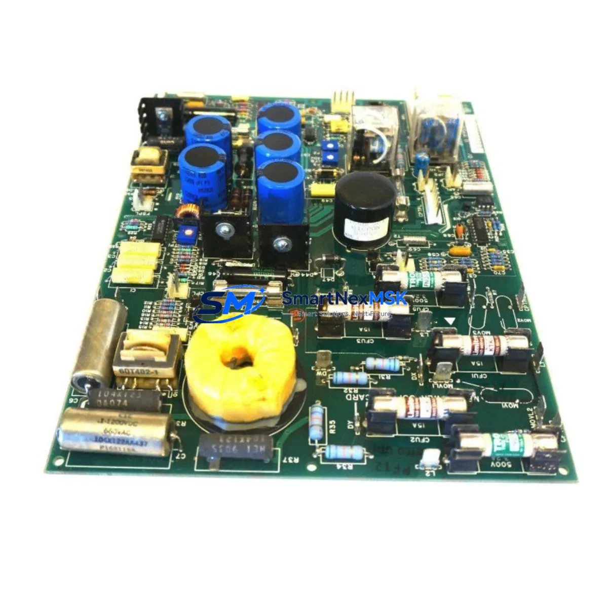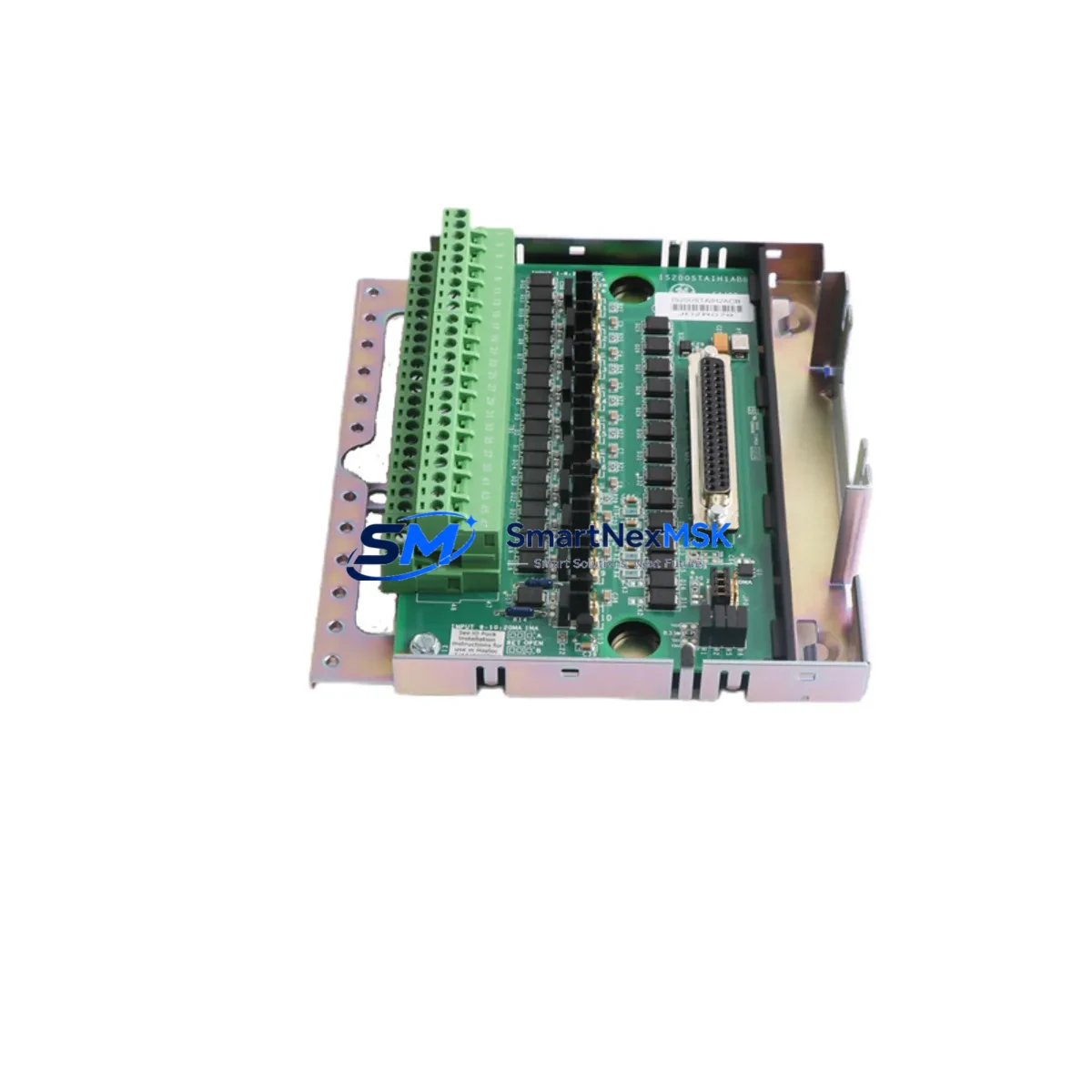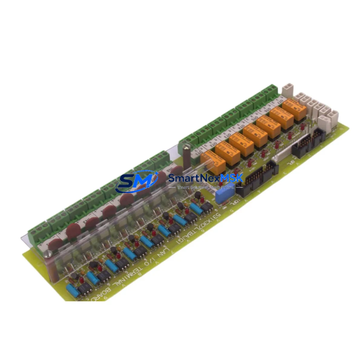
GE 531X307LTBAJG1 Retrofit-Ready Drive Control for Mark V Control Systems
The GE 531X307LTBAJG1 is a Drive Control PC Board engineered for the GE Mark V turbine and drive control platform — one of the most widely deployed industrial control architectures in power generation, oil & gas, and heavy manufacturing. As the Mark V series approaches end-of-life and original spare inventories diminish, the 531X307LTBAJG1 has become a critical retrofit component for facilities seeking to extend system life, restore failed control loops, and avoid the cost and complexity of full platform migration.
Whether you are replacing a failed board in an emergency shutdown scenario or executing a planned control cabinet upgrade, the 531X307LTBAJG1 provides a direct-fit, wiring-compatible solution that preserves your existing rack architecture, terminal assignments, and program logic. This board is sourced, inspected, and tested prior to shipment, backed by a 12-month warranty, and available from stock for rapid deployment.
Upgrade Compatibility Table
| Parameter | Details |
|---|---|
| SKU / Part Number | 531X307LTBAJG1 |
| Manufacturer | General Electric (GE) |
| Series | Mark V Drive Control Platform |
| Product Type | Drive Control PC Board |
| Form Factor | Rack-mount PCB, Mark V backplane compatible |
| Interface Compatibility | Mark V I/O rack, IONET / ARCNET communication bus |
| Replacement Scope | Direct replacement for failed or obsolete 531X307LTBAJG1 boards |
| Wiring Compatibility | Existing terminal block and field wiring retained without modification |
| Communication Protocol | Compatible with Mark V IONET serial communication architecture |
| Power Supply Requirement | Supplied via Mark V backplane; verify PSIO or TCEA power module output |
| Installation Environment | Industrial control cabinet; operating temp 0–55°C, humidity ≤95% non-condensing |
| Pre-Shipment Testing | Functional test performed on each unit before dispatch |
| Warranty | 12 Months |
| Origin | United States |
| Stock Status | Available — ships within 2–5 business days |
Retrofit Planning for Existing Automation Systems
A successful retrofit of the 531X307LTBAJG1 requires a systematic review of the surrounding control architecture before the replacement board is installed. Maintenance and procurement engineers should begin by auditing the Mark V rack configuration — confirming that the backplane, card cage, and adjacent boards such as the VCMI (Voter Communication Module Interface) and STCA (Simplex Turbine Control Application) boards are in serviceable condition. A failed drive control board rarely fails in isolation; thermal stress, power transients, and communication faults often affect neighboring modules simultaneously.
The PSIO (Power Supply I/O) module and TCEA (Turbine Control Electronics Assembly) power distribution board should be inspected and load-tested before the new 531X307LTBAJG1 is seated. Insufficient or unstable backplane power is a leading cause of premature board failure in aging Mark V cabinets. Verify that the 28VDC and 5VDC rails are within specification using a calibrated multimeter before powering the replacement board.
Field wiring connected to the terminal boards — including the TBCI (Terminal Board for Control Inputs) and TBQC (Quick-Connect Terminal Board) assemblies — should be inspected for insulation degradation, loose terminations, and correct labeling. In many retrofit scenarios, the original wiring documentation is incomplete or outdated; a full point-to-point continuity check is strongly recommended before commissioning the replacement board.
Communication integrity is equally critical. The Mark V IONET or ARCNET communication bus links the drive control board to the operator HMI (typically a GE Cimplicity workstation) and to peer controllers in redundant configurations. After board replacement, verify that the node address DIP switch settings on the 531X307LTBAJG1 match the original configuration. A mismatch will cause the board to fail to join the control network, resulting in a persistent fault alarm and loss of drive control visibility at the HMI.
For sites running GE ToolboxST or the legacy Mark V configuration software, a configuration download to the replacement board may be required. Ensure that the site’s configuration file is archived and version-controlled before any retrofit work begins. If the original configuration file is unavailable, SMARTNEXMSK can assist in sourcing reference configurations for common Mark V drive applications.
Finally, I/O signal verification should be performed after board installation and before returning the drive to service. Analog input channels — including speed feedback, current feedback, and temperature signals — should be loop-tested using a signal injector. Digital output channels controlling contactors, relays, and gate drive signals should be verified against the original functional test procedure. Related components commonly involved in this verification process include the IS200VCMIH2C communication module, IS200TCEAH1A turbine control electronics board, IS200PSICH1A power supply interface card, IS200TBCIH1C terminal board, and the Mark V HMI operator workstation — all of which may require simultaneous inspection or replacement during a comprehensive cabinet overhaul.
Downtime Control During System Migration
Unplanned downtime during a Mark V drive control board replacement can be minimized through disciplined pre-work and a structured hot-swap protocol. The following approach is recommended for maintenance teams executing a 531X307LTBAJG1 replacement under time pressure:
Step 1 — Pre-replacement audit: Before de-energizing the cabinet, capture a full screenshot or printout of the HMI alarm summary, active setpoints, and drive status. This baseline record is essential for post-replacement verification and reduces commissioning time significantly. If your site uses a GE Cimplicity SCADA system or a Mark V WorkstationST, export the current tag database and alarm configuration before proceeding.
Step 2 — Safe isolation: Follow the site’s lockout/tagout (LOTO) procedure for the Mark V cabinet. Confirm that the drive is in a safe, de-energized state before opening the card cage. The Mark V backplane carries live voltages even when the drive is stopped — do not assume the rack is de-energized based on drive status alone.
Step 3 — Board extraction and inspection: Remove the failed 531X307LTBAJG1 carefully, noting the DIP switch positions, jumper configurations, and any visible damage. Photograph the board before removal for reference. Inspect the backplane connector for bent pins or corrosion. If the IS200VCMIH2C communication module or adjacent I/O boards show signs of thermal damage, plan for their replacement in the same maintenance window.
Step 4 — Replacement board preparation: Configure the replacement board’s DIP switches and jumpers to match the extracted board before installation. This step is frequently overlooked and is the most common cause of post-replacement communication faults on the IONET bus.
Step 5 — Installation and power-up: Seat the replacement board firmly into the backplane, restore power, and monitor the Mark V diagnostic LEDs for normal boot sequence. A successful boot is indicated by the green RUN LED illuminating within 30–60 seconds. If a fault LED persists, consult the Mark V fault code reference before proceeding. The IS200PSICH1A power supply interface card status LEDs should also be checked to confirm stable backplane power delivery.
Step 6 — Functional verification: Perform a no-load drive test, verify HMI communication, confirm all I/O channels are reading correctly, and clear any residual fault alarms. Document the replacement in the site’s maintenance log with the new board’s serial number and installation date. For sites with redundant Mark V racks, verify that the replacement board has successfully joined the TMR voting group before returning the unit to automatic control.
By following this structured workflow, most Mark V drive control board replacements can be completed within a 4–8 hour maintenance window, minimizing production impact and ensuring a reliable return to service.
Retrofit Support FAQ
Q1: Is the 531X307LTBAJG1 a direct drop-in replacement for the original GE Mark V board?
Yes. The 531X307LTBAJG1 is designed as a direct replacement for the original board of the same part number used in GE Mark V drive control systems. No rack modification, wiring change, or backplane adapter is required. DIP switch and jumper settings must be matched to the original configuration before installation.
Q2: What pre-shipment testing is performed on each unit?
Every 531X307LTBAJG1 supplied by SMARTNEXMSK undergoes a functional test prior to dispatch. This includes power-on verification, communication bus integrity check, and I/O channel continuity testing. A test report is available upon request. All units are covered by a 12-month warranty from the date of shipment.
Q3: Can this board be used in a Mark V redundant (TMR) configuration?
The 531X307LTBAJG1 is compatible with both simplex and TMR (Triple Modular Redundant) Mark V configurations, subject to the specific rack and software version in use at your site. Please provide your Mark V system configuration details when ordering to allow our technical team to confirm compatibility before shipment.
Q4: What is the lead time and warranty coverage?
Units are available from stock and typically ship within 2–5 business days. A 12-month warranty covers manufacturing defects and functional failures under normal operating conditions. Expedited shipping is available for emergency breakdown situations — contact our team directly to arrange priority dispatch.
© 2026 SMARTNEXMSK. All rights reserved.
Original Source: https://smartnexmsk.com
Contact: [email protected] | +86 18259474341