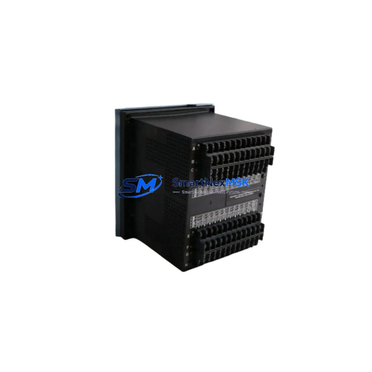
GE 745-W3-P511-G51-HI-R-E-H Maintenance-Ready Spare for 745 Automation
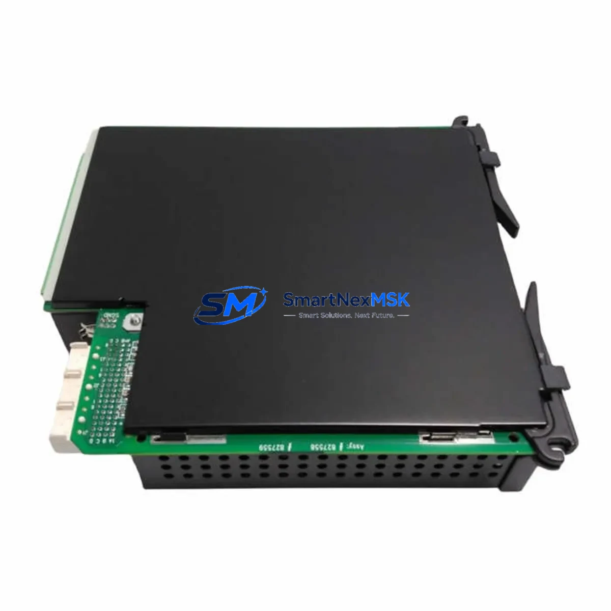
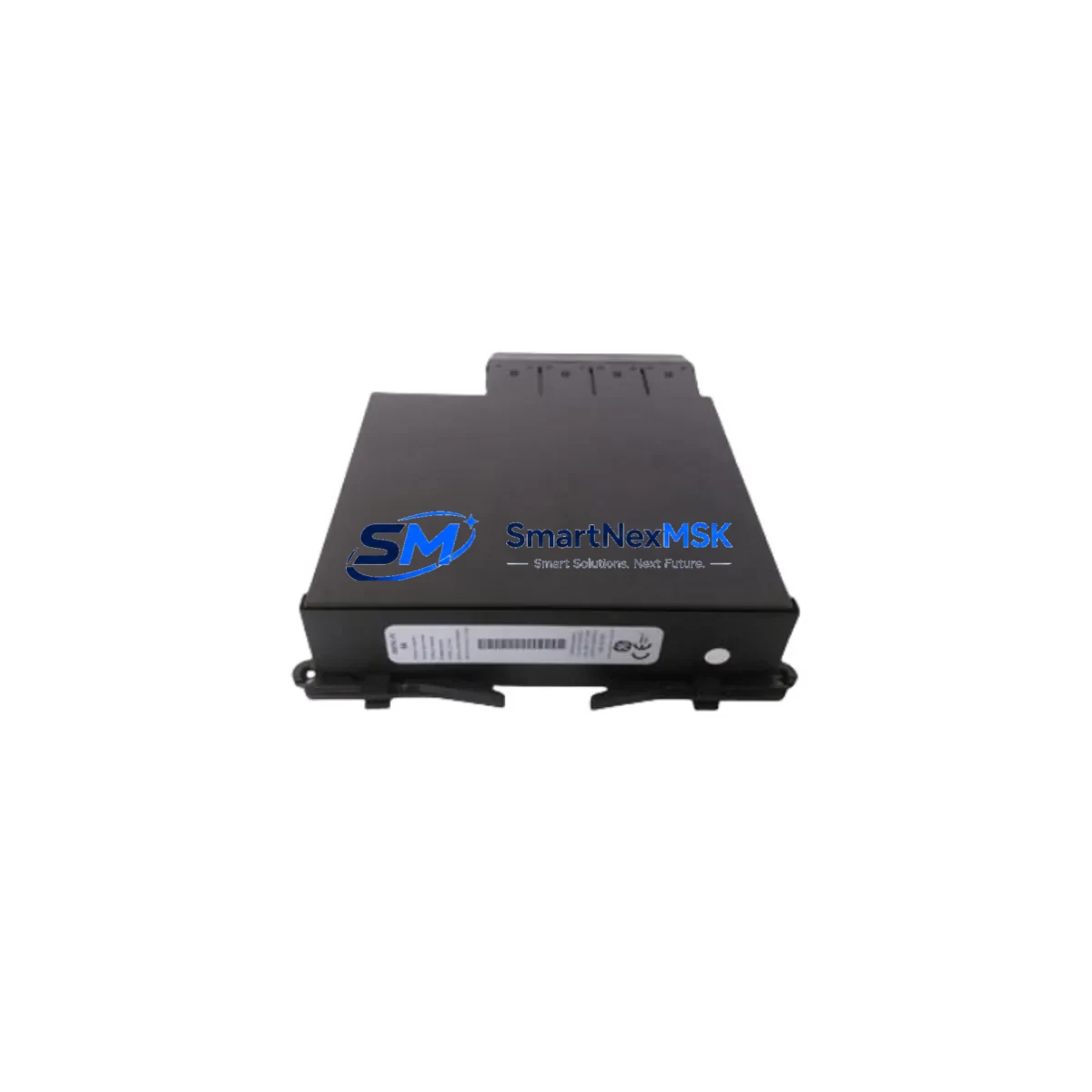
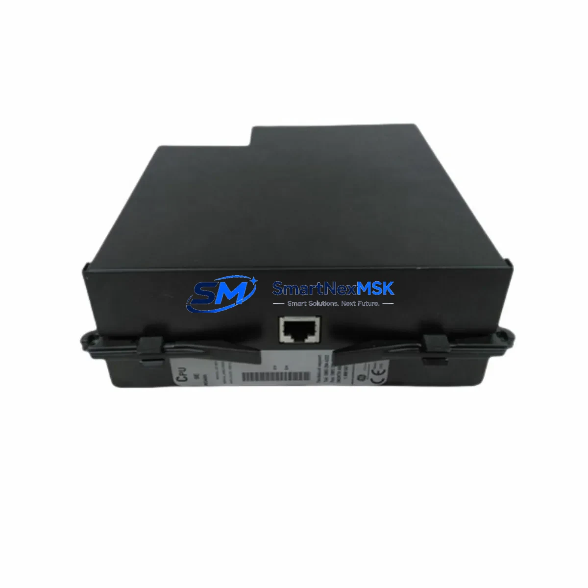
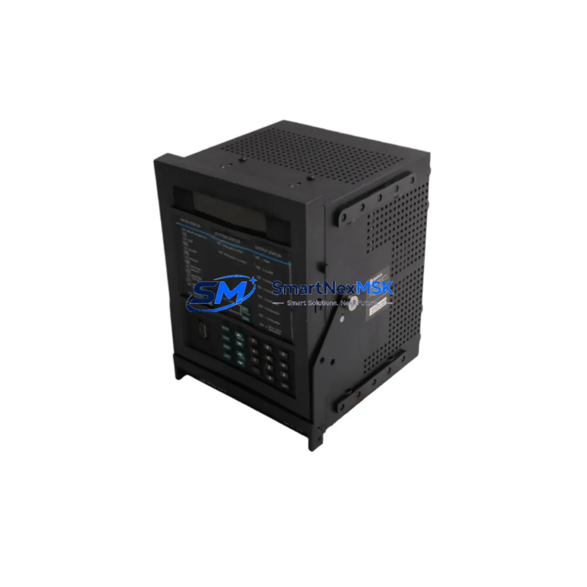
The GE Multilin 745-W3-P511-G51-HI-R-E-H is a fully featured transformer protection relay from GE Grid Solutions’ 745 series, engineered for critical power transformer protection in industrial substations, utility switchgear, and heavy manufacturing environments. As a maintenance-ready original spare, this unit is pre-tested, configuration-verified, and ready for immediate deployment to minimize transformer feeder downtime and restore protection coverage without delay.
Maintenance engineers and procurement teams managing aging transformer protection systems rely on the 745 series for its comprehensive differential, overcurrent, and thermal protection functions. When a 745 relay requires replacement — whether due to firmware obsolescence, hardware fault, or planned lifecycle refresh — having a verified original spare on hand is the single most effective strategy for reducing mean time to repair (MTTR) and avoiding unplanned outages that cascade into production losses.
This unit supports the full 745 protection function set including transformer differential (87T), restricted earth fault (REF), overcurrent (50/51), thermal overload (49), and breaker failure (50BF). The W3 designation confirms a wide-range AC power supply input, P511 indicates the standard I/O configuration with five current inputs and one voltage input, G51 specifies the communications and I/O expansion, HI denotes high-impedance differential inputs, R confirms RTD/thermocouple thermal monitoring inputs, E indicates Ethernet communications capability, and H specifies the high-speed output relay configuration. This combination makes the 745-W3-P511-G51-HI-R-E-H one of the most capable and widely deployed transformer protection platforms in the GE Multilin portfolio.
Spare Maintenance Table
| SKU / Part Number | 745-W3-P511-G51-HI-R-E-H |
| Brand / Manufacturer | GE Grid Solutions (GE Multilin) |
| Series | 745 Transformer Management Relay |
| Product Type | Transformer Protection Relay (IED) |
| Protection Functions | 87T Differential, REF, 50/51 Overcurrent, 49 Thermal, 50BF Breaker Failure, 27/59 Voltage |
| Power Supply Input | Wide-range AC (W3 designation) |
| Current Inputs | 5 CT inputs (P511 configuration) |
| Thermal Monitoring | RTD / Thermocouple inputs (R designation) |
| Communications | Ethernet (E designation), RS-485 Modbus, DNP3 |
| Output Relays | High-speed output configuration (H designation) |
| High-Impedance Differential | Yes (HI designation) |
| Mounting | 19″ rack / panel flush mount, standard 745 cutout |
| Operating Temperature | -20°C to +60°C |
| Application Environment | Industrial substation, utility switchgear, heavy manufacturing |
| Compatibility | Direct replacement for all 745 series variants; compatible with EnerVista 745 PC software |
| Origin | Canada (GE Grid Solutions manufacturing) |
| Condition | Original, tested prior to shipment |
| Warranty | 12 Months |
Maintenance Planning for Continuous Operation
When scheduling a 745-W3-P511-G51-HI-R-E-H replacement during a planned outage window or responding to an emergency trip event, a disciplined maintenance engineer will not stop at the relay itself. The 745 relay sits at the center of a transformer protection circuit that depends on the integrity of every upstream and downstream component. A thorough site inspection and spare parts review should cover the following associated components:
Current Transformer (CT) secondary wiring and terminal blocks feeding the five current inputs should be inspected for insulation degradation, loose terminations, and correct polarity. Damaged CT wiring is a common root cause of spurious differential trips that are incorrectly attributed to relay malfunction. Auxiliary power supply modules providing the relay’s wide-range AC input should be verified for output voltage stability — a drifting auxiliary supply can cause relay resets that mimic hardware failure.
The RTD/thermocouple input wiring connected to the R-designation thermal monitoring inputs should be continuity-tested and compared against the transformer’s winding temperature indicators. Faulty RTD circuits will suppress thermal protection and create an undetected overload risk. Output relay wiring to trip coils on the associated HV and LV circuit breakers must be verified for continuity and correct trip coil resistance — a failed trip coil will prevent the 745 from clearing a fault even when the relay operates correctly.
For sites using the Ethernet communications port, the managed Ethernet switch or communications gateway connecting the 745 to the SCADA or DCS network should be inspected for port activity and correct VLAN configuration. Loss of communications does not prevent protection operation but will blind the control room to relay status and event records. RS-485 Modbus or DNP3 communication cables and termination resistors should also be checked if the site uses serial SCADA integration alongside or instead of Ethernet.
The test switch or relay test block (if installed) used for secondary injection testing should be exercised to confirm it operates freely and makes clean contact — a corroded test block can introduce resistance into the CT secondary circuit. Fuses or miniature circuit breakers protecting the relay’s auxiliary power supply and trip output circuits should be replaced as a matter of course during any relay changeout. Terminal strip and DIN rail assemblies within the protection panel should be inspected for tracking, discoloration, or loose screws that could cause intermittent connections under vibration.
Finally, if the 745 is part of a broader transformer management system, the EnerVista 745 PC software settings file should be retrieved from the outgoing relay before removal, verified against the as-built protection coordination study, and loaded into the replacement unit before energization. Maintaining a current settings backup is a non-negotiable element of any 745 spare parts strategy.
Site Replacement Workflow
Step 1 — Pre-outage preparation: Retrieve the existing relay’s settings file using EnerVista 745 software. Confirm the replacement unit’s firmware version is compatible with the settings file version. If a firmware upgrade is required, perform it on the bench before the outage window begins.
Step 2 — Isolation and de-energization: Follow the site’s switching schedule to isolate the transformer and associated HV/LV breakers. Apply earthing as required. Confirm the relay’s auxiliary supply is de-energized before opening the panel.
Step 3 — CT secondary shorting: Short all CT secondary circuits at the test block or terminal strip before disconnecting the relay. Never open a CT secondary circuit under load — this is a critical safety step that prevents dangerous overvoltage on the CT secondary.
Step 4 — Relay removal and inspection: Disconnect all wiring, label each terminal, and remove the outgoing relay. Inspect the panel interior for signs of overheating, tracking, or moisture ingress. Replace any suspect terminal blocks, fuses, or wiring before installing the replacement unit.
Step 5 — Replacement installation: Mount the 745-W3-P511-G51-HI-R-E-H in the existing cutout. Reconnect all wiring per the as-built drawings. Remove CT secondary shorts. Apply auxiliary power and confirm the relay powers up without alarm.
Step 6 — Settings load and commissioning: Load the verified settings file via EnerVista 745. Perform a secondary injection test to confirm all protection elements operate at the correct thresholds. Confirm communications to SCADA/DCS. Document the commissioning test results before returning the transformer to service.
This workflow is applicable whether replacing a failed unit on an emergency basis or executing a planned lifecycle replacement of an aging 745 relay. The 745-W3-P511-G51-HI-R-E-H is a direct form-fit-function replacement for all 745 series variants, eliminating the need for panel modifications or wiring changes in the vast majority of installations.
Spare Parts Support FAQ
Q1: What is the recommended spare parts holding strategy for the GE 745 series?
For critical transformer protection applications, a minimum of one 745 spare relay per substation or per five installed units is recommended. Given that the 745 series has been in production for over two decades and some sites operate legacy variants that are no longer available through standard distribution channels, securing original spares now is a prudent risk management decision. Our long-term supply capability covers both current production variants and legacy 745 configurations.
Q2: How is the 745-W3-P511-G51-HI-R-E-H tested before shipment?
Each unit undergoes a pre-shipment functional test covering power-up self-diagnostics, communications port verification, output relay operation, and input circuit continuity. Units that do not pass all test criteria are not shipped. A test report is available upon request for critical applications.
Q3: Can this unit replace a 745 variant with a different option code?
The 745 option code string defines the hardware configuration. Substituting a unit with a different option code is possible in some cases — for example, a unit with additional I/O options can replace a base-configuration unit — but requires a careful comparison of the as-built wiring and settings file against the replacement unit’s hardware capabilities. We recommend providing your existing relay’s full option code and settings file for a compatibility assessment before ordering if you are uncertain.
Q4: What does the 12-month warranty cover?
The 12-month warranty covers hardware defects and functional failures under normal operating conditions. It does not cover damage resulting from incorrect installation, overvoltage events, or failure to follow the site replacement workflow. Warranty claims are supported by our technical team with a target response time of one business day. Replacement units are dispatched promptly to minimize any extended downtime exposure.
© 2026 SMARTNEXMSK. All rights reserved.
Original Source: https://smartnexmsk.com
Contact: [email protected] | +86 18259474341