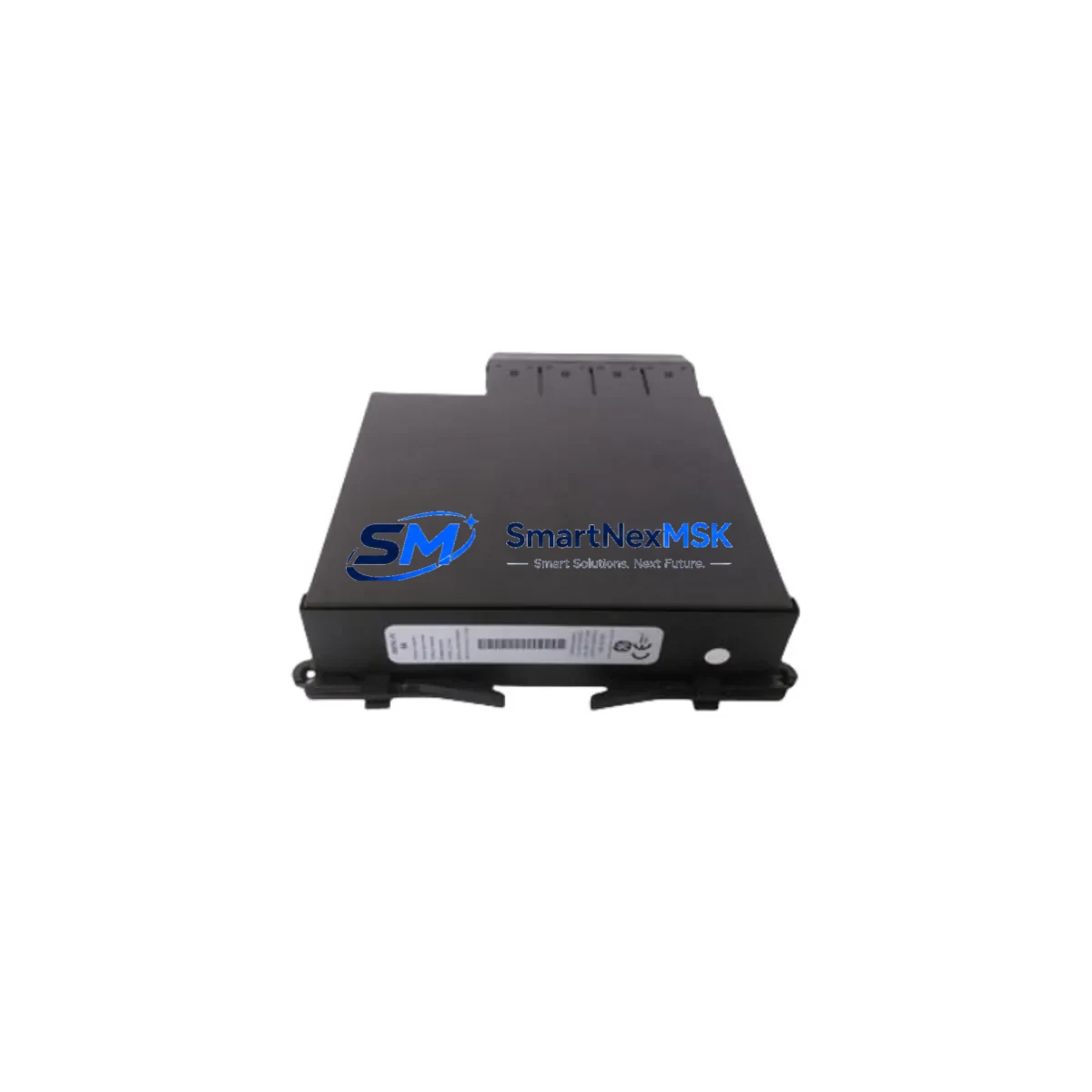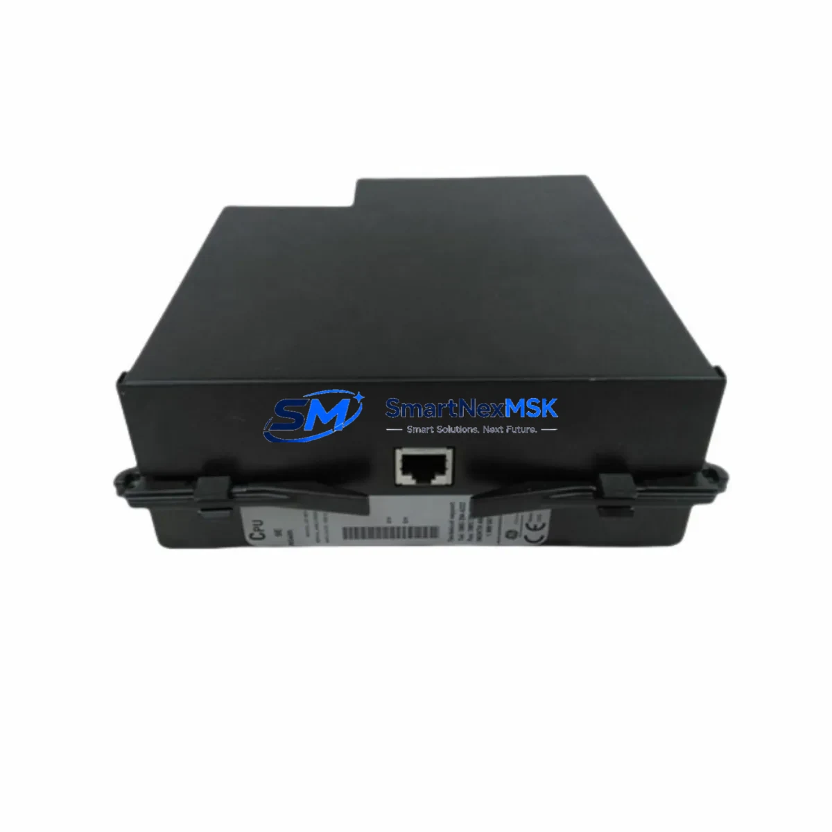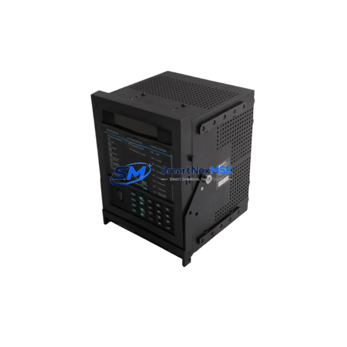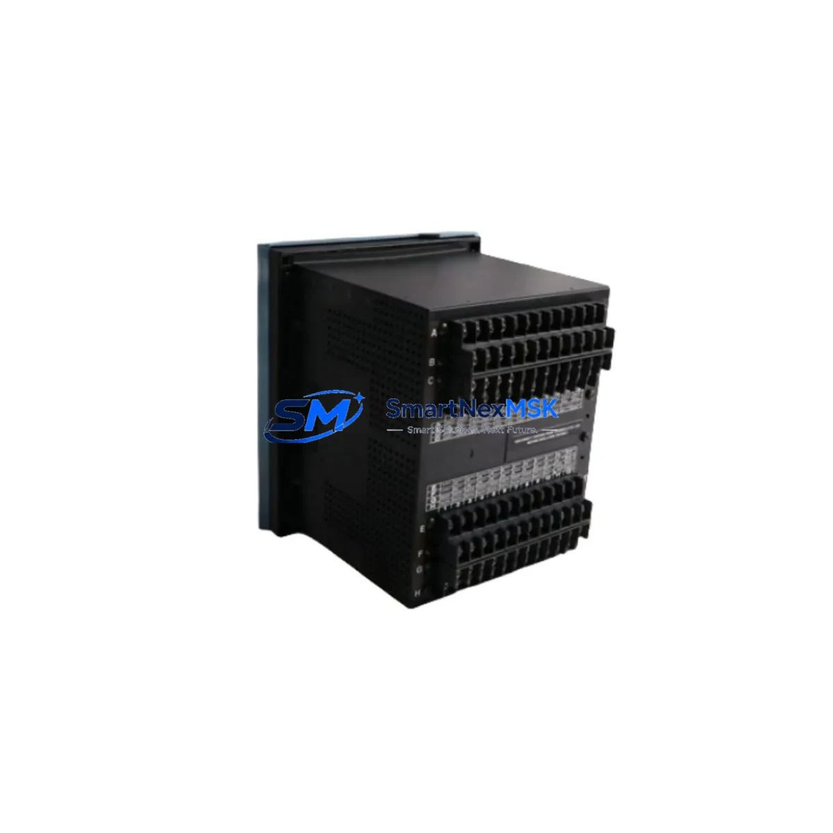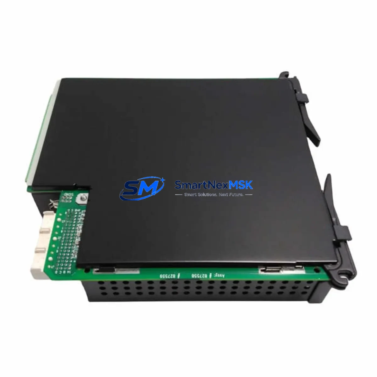
GE UR-RHH Retrofit-Ready I/O Module for UR Series Control Systems
The GE UR-RHH is a Digital I/O Expansion Module engineered for the GE Universal Relay (UR) Series protection and control platform. As legacy relay panels age and OEM support windows close, the UR-RHH provides a verified, drop-in retrofit path for substations, switchgear cabinets, and industrial protection systems that must maintain continuous operation during modernization. Whether you are replacing a failed module, upgrading an end-of-life relay chassis, or migrating from an older GE SR/DFP platform to the current UR architecture, the UR-RHH delivers the I/O density and backplane compatibility required to complete the transition with minimal downtime. Every unit shipped by SMARTNEXMSK is pre-shipment tested and backed by a 12-month warranty.
Upgrade Compatibility Table
| Parameter | Details |
|---|---|
| Compatible Platform | GE Universal Relay (UR) Series – F35, F60, L90, T60, D60, C60, B30, B90 |
| Module Type | Digital I/O Expansion (Contact Input / Output) |
| Backplane Interface | UR-Series rear-mount backplane slot; keyed connector, no adapter required |
| Chassis Form Factor | UR-8H and UR-6H chassis; confirm slot assignment in EnerVista UR Setup |
| Installation Requirement | Standard UR chassis slot; verify slot number in EnerVista UR Setup software before download |
| Communication Compatibility | IEC 61850 GOOSE, DNP3, Modbus RTU/TCP – inherited from host UR relay |
| Replacement Recommendation | Direct replacement for failed or end-of-life UR-RHH; host relay firmware ≥ 7.4x recommended |
| Commissioning Focus | Contact input threshold voltage, output relay coil wiring, module address in EnerVista |
| Pre-Shipment Test | Functional I/O test across all input voltage thresholds and output relay ratings; report on request |
| Warranty | 12 Months – covers manufacturing defects from date of shipment |
Retrofit Planning for Existing Automation Systems
A successful UR-RHH retrofit begins well before the module arrives on site. Engineers should pull the existing relay’s EnerVista UR Setup configuration file and document every contact input assignment, output relay mapping, and virtual output (VO) binding before powering down the chassis. The UR-RHH slots into the same rear-mount backplane position as the original module; however, the slot number must be re-confirmed in the settings file because chassis configurations vary between the UR-8H and UR-6H chassis form factors.
Power budget verification is a critical pre-installation step. The UR chassis power supply — typically a UR-PSM or UR-PSH power supply module — must have sufficient headroom to support the additional I/O load. Review the chassis power allocation table in the UR Hardware Manual (GEK-113000) and confirm that the aggregate draw of all installed modules, including the UR-RHH, does not exceed the supply’s rated output. If the existing supply is already near capacity, a UR-PSH high-capacity replacement should be sourced concurrently to avoid nuisance trips during commissioning.
Terminal wiring on the UR-RHH follows the standard UR rear-terminal block layout. Each contact input circuit must be wired to the correct terminal pair and the wet/dry input mode jumper set to match the field voltage — typically 24 VDC, 48 VDC, 110 VDC, or 125 VDC depending on the substation DC bus. Output relay terminals are rated for the trip and close coil currents of the associated circuit breaker; verify that the coil current does not exceed the UR-RHH output contact rating before energizing. Terminal block adapters, if used, must be cross-referenced against the UR-RHH terminal numbering in GEK-113000 before any wiring is disturbed.
For sites migrating from older GE SR750 or GE SR469 motor protection relays to the UR platform, the I/O point count and terminal numbering will differ significantly. A terminal-by-terminal cross-reference drawing should be prepared before any wiring is disturbed. The GE UR-GTNET communications card, if installed in the same chassis, must also be reconfigured to reflect any changes to the GOOSE dataset or DNP3 point list that result from the new I/O module slot assignment. Where the site runs a mixed-protocol environment — for example, legacy Modbus RTU alongside IEC 61850 — the UR-GTNET-2 dual-port communications module provides the protocol bridging needed to maintain SCADA visibility during the transition period.
HMI screens connected via the GE D20MX substation controller or a third-party SCADA front-end should be reviewed for any hardcoded point references that map to the replaced module’s I/O addresses. Update the DNP3 or IEC 61850 data model in the SCADA configuration to reflect the new module slot assignment before returning the protection system to service. Sites operating mixed-generation UR chassis — for example, a UR-F60 feeder protection relay alongside a legacy GE DFP digital feeder protection unit — should plan the UR-RHH installation as part of a broader panel standardization project. Standardizing on the UR backplane architecture simplifies spare-parts inventory, reduces training overhead, and enables unified IEC 61850 substation automation across all protection zones. A GE UR-9xx programming cable and a laptop running EnerVista UR Setup are the only additional tools required for on-site commissioning.
Downtime Control During System Migration
Minimizing protection system downtime during a UR-RHH swap requires a structured, pre-planned procedure. Where the substation topology permits, transfer load to an alternate feeder or bus section before de-energizing the affected relay panel. Back up the full relay settings file from EnerVista UR Setup immediately before the outage window begins — this file is the single most important asset for rapid restoration if commissioning issues arise. Confirm that the replacement UR-RHH firmware revision is compatible with the host relay before the outage is scheduled; a firmware mismatch discovered on-site will extend the outage window significantly.
With the chassis de-energized, remove the failed or end-of-life UR-RHH by releasing the module locking tabs and sliding it clear of the backplane. Inspect the backplane connector for bent pins or contamination before inserting the replacement module. Seat the UR-RHH firmly until the locking tabs engage, then restore chassis power. EnerVista UR Setup will detect the new module automatically; confirm that the slot assignment matches the original configuration file before downloading settings to the relay.
Perform a contact input continuity check using the relay’s built-in test mode before reconnecting field wiring. Verify each output relay operates correctly by issuing a forced output command from EnerVista and confirming the associated circuit breaker or contactor responds as expected. Log all test results in the site commissioning record. Once all I/O points are verified, restore the protection system to service and notify the SCADA operator to confirm that all points are reading correctly at the control center. For a well-prepared team with a pre-staged replacement module and a current settings backup, total outage time for a single UR-RHH replacement is typically 2–4 hours. Inventory availability and same-week dispatch from SMARTNEXMSK stock further reduce the risk of extended unplanned outages caused by long lead times on obsolete spare parts.
Retrofit Support FAQ
Q1: Is the UR-RHH a direct drop-in replacement for all UR Series chassis?
The UR-RHH is compatible with all standard UR Series chassis that support rear-mount I/O expansion slots, including the UR-8H and UR-6H form factors. Confirm the target slot number and chassis firmware revision (≥ 7.4x recommended) before installation. Some early UR chassis revisions may require a firmware update on the host relay to recognize the module correctly. Contact SMARTNEXMSK with your chassis serial number for a pre-sale compatibility check.
Q2: What pre-shipment testing is performed on the UR-RHH?
Every UR-RHH unit shipped by SMARTNEXMSK undergoes a functional I/O test that verifies contact input detection across all supported voltage thresholds (24 VDC, 48 VDC, 110 VDC, 125 VDC) and output relay operation under rated coil current. A test report is available on request. All units are covered by a 12-month warranty against manufacturing defects from the date of shipment.
Q3: How do I verify wiring compatibility between the UR-RHH and my existing terminal blocks?
The UR-RHH uses the standard UR rear-terminal block layout documented in GEK-113000. Compare the terminal assignment table in the hardware manual against your existing wiring schedule. Pay particular attention to the contact input wet/dry mode jumper setting and the output relay terminal polarity. If your panel uses custom terminal block adapters, verify that the adapter pinout matches the UR-RHH terminal numbering before energizing. SMARTNEXMSK can provide a wiring cross-reference template on request.
Q4: Can the UR-RHH be used in a system that also runs IEC 61850 GOOSE messaging?
Yes. The UR-RHH I/O points can be mapped to GOOSE datasets configured in EnerVista UR Setup. The GOOSE configuration is managed at the host relay level via the UR-GTNET communications card; the UR-RHH itself does not require separate network configuration. After installation, update the IEC 61850 data model export and re-import it into your substation automation system to reflect any changes to the I/O dataset. All GOOSE subscriptions referencing the affected relay should be re-tested before returning the system to service.
© 2026 SMARTNEXMSK. All rights reserved.
Original Source: https://smartnexmsk.com
Contact: [email protected] | +86 18259474341