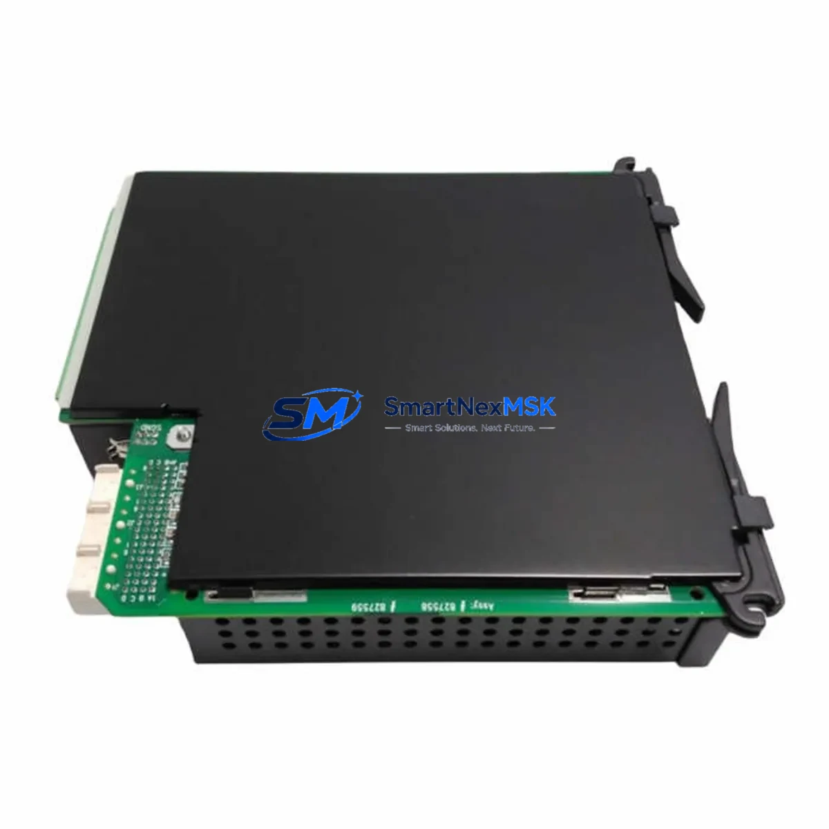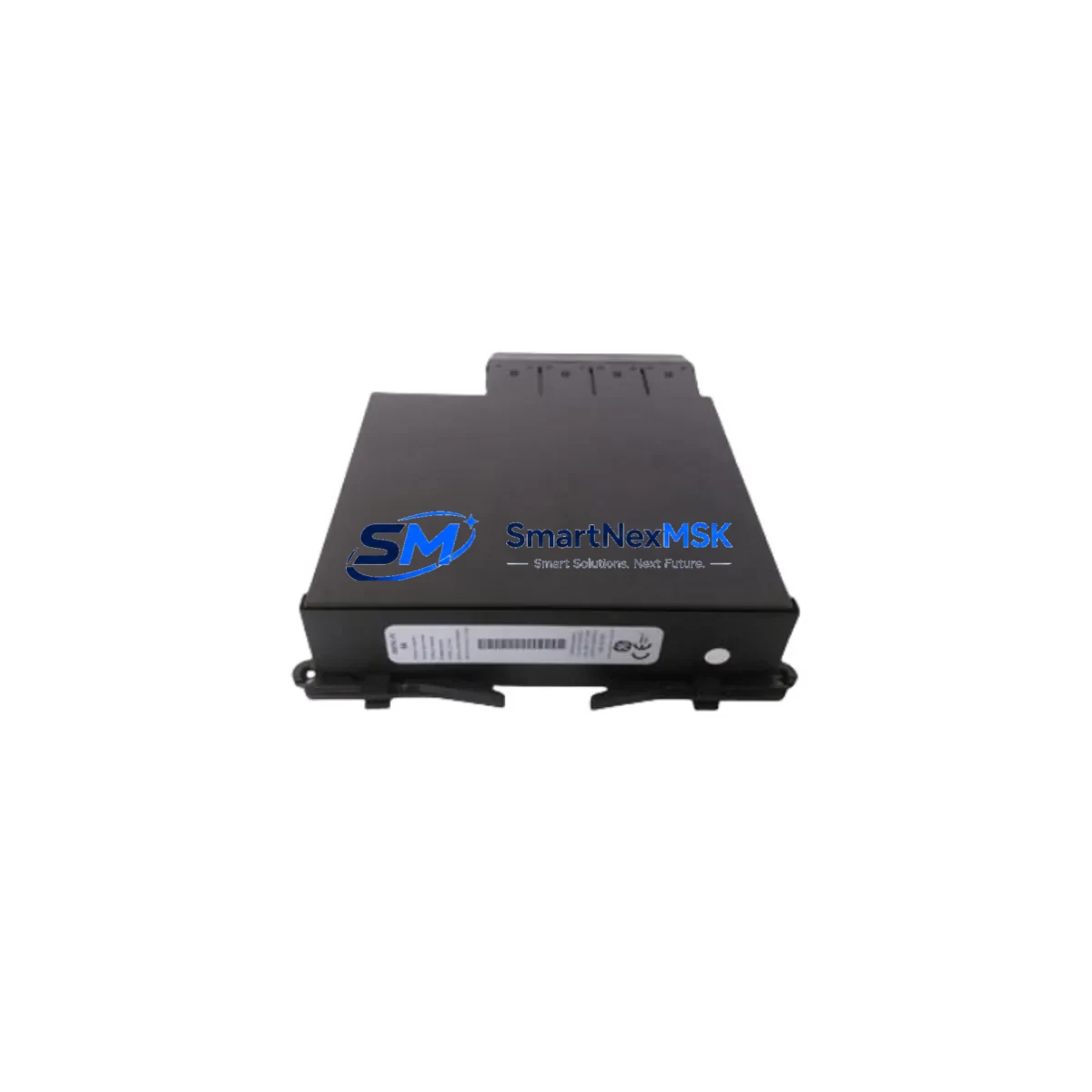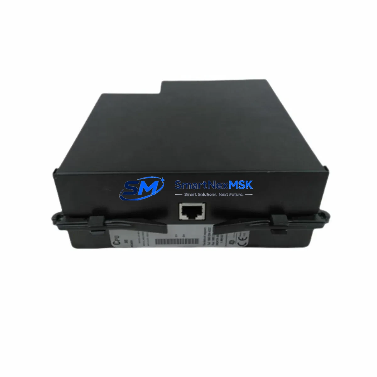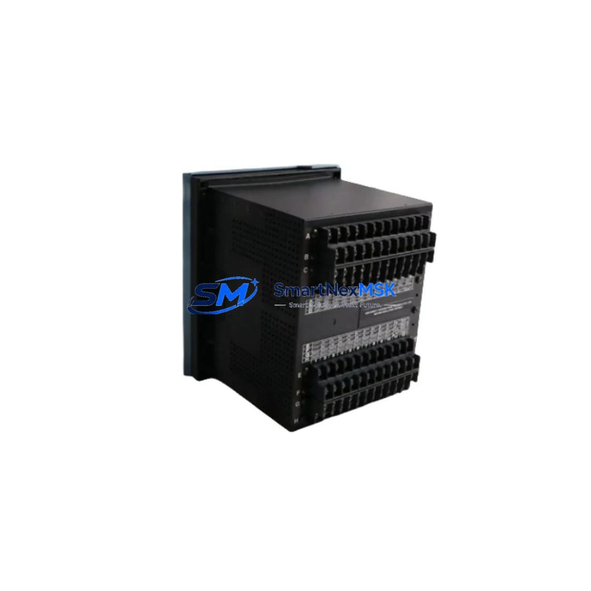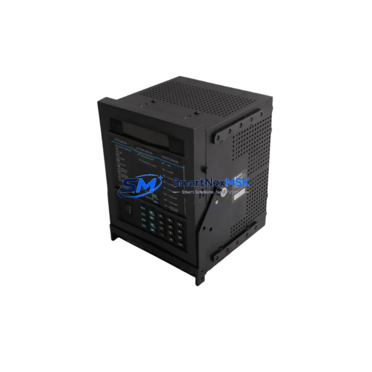
GE Multilin 750-P5-G5-D5-HI-A1-R Retrofit-Ready Transformer Protection Relay for Legacy Control Systems
The GE Multilin 750-P5-G5-D5-HI-A1-R is a full-featured transformer protection relay engineered for both new installations and the modernization of aging power protection infrastructure. As a direct retrofit candidate for legacy GE Multilin 750 Series deployments, this relay supports seamless migration from discontinued or end-of-life protection hardware without requiring a complete panel redesign. Whether you are upgrading a substation control cabinet, replacing a failed relay in a critical transformer bay, or migrating from an older electromechanical or first-generation numerical relay, the 750-P5-G5-D5-HI-A1-R delivers the compatibility, configurability, and reliability that industrial and utility engineers demand.
This model carries the following option codes: P5 (5A CT input), G5 (ground fault, 5A), D5 (differential, 5A), HI (harmonic inhibit), A1 (RS-485 communications), and R (redundant power supply). These options make it particularly well-suited for transformer differential protection applications where harmonic restraint during energization and reliable serial communications to a SCADA or DCS host are required.
Upgrade Compatibility Table
| Parameter | Details |
|---|---|
| SKU / Model | 750-P5-G5-D5-HI-A1-R |
| Series | GE Multilin 750 Series |
| Primary Function | Transformer Differential & Overcurrent Protection |
| CT Input Rating | 5A (P5, G5, D5 options) |
| Communications | RS-485 / Modbus RTU (A1 option) |
| Power Supply | Redundant (R option) — 85–265 VAC/VDC |
| Harmonic Inhibit | Yes (HI option) — 2nd & 5th harmonic restraint |
| Mounting | 19″ rack or panel flush mount; standard 750 Series cutout |
| Backplane / Rack | Compatible with existing GE Multilin 750 Series panel cutouts |
| Terminal Wiring | Rear screw-terminal block; compatible with existing 750 Series wiring harness |
| Protocol Migration | Modbus RTU via RS-485; upgrade path to IEC 61850 available with 750-A2 variant |
| Replacement Candidates | GE Multilin 745, 350, SR750, and first-generation 750 variants |
| Commissioning Notes | Requires CT ratio verification, differential slope setting, and Modbus node address assignment |
| Warranty | 12 Months — covers manufacturing defects, functional failure, and firmware integrity |
Retrofit Planning for Existing Automation Systems
Successful integration of the 750-P5-G5-D5-HI-A1-R into an existing protection scheme begins with a thorough audit of the outgoing relay’s wiring schedule and settings file. In most legacy installations, the transformer bay will include a GE Multilin 745 transformer protection relay or an older SR750 variant as the primary differential element. The 750-P5-G5-D5-HI-A1-R is dimensionally and functionally compatible with these predecessors, sharing the same rear terminal layout for CT inputs, trip output contacts, and alarm wiring.
Before removal of the existing relay, engineers should export the current settings using EnerVista 750 Setup software and document all active protection elements, CT ratios, pickup thresholds, and time-delay curves. The replacement relay can be pre-configured offline and bench-tested against the exported settings file prior to installation, significantly reducing panel downtime.
In control cabinets where the 750-P5-G5-D5-HI-A1-R shares a rack with other protection and monitoring devices, it is common to find companion modules such as a GE Multilin 350 feeder protection relay for downstream feeder protection, a GE Multilin 469 motor protection relay for associated motor loads, and a GE Multilin 239 motor protection relay for smaller auxiliary motors. The RS-485 Modbus RTU bus (A1 option) allows all of these devices to share a single serial communications trunk back to the plant DCS or SCADA system — typically a GE iFIX SCADA or Wonderware InTouch HMI platform. When replacing the relay, the Modbus node address must be reassigned to match the original device address stored in the HMI tag database to avoid communication faults and alarm floods on the operator workstation.
Power supply integrity is a critical pre-installation check. The redundant power supply option (R) accepts a wide input range of 85–265 VAC/VDC, making it compatible with both 110 VAC station service and 125 VDC battery-backed control power common in substation environments. Verify that the existing panel’s control power bus can support the relay’s burden before energizing. In older installations, the control power distribution board may also supply a GE Multilin EPM 7000 power meter or a GE Reason RT430 merging unit — confirm that adding the new relay does not exceed the panel’s total VA budget.
For I/O expansion requirements, the 750 Series supports optional I/O modules that can be field-installed to add digital inputs, output contacts, or analog channels. If the legacy installation used external GE Multilin 750-I/O expansion modules or third-party relay output terminal blocks, verify that the new relay’s I/O map matches the existing wiring before closing the panel. Label all terminal blocks clearly and photograph the wiring before disconnection — this is standard practice for any protection relay retrofit and is essential for post-commissioning verification.
Downtime Control During System Migration
Minimizing unplanned outage duration is the primary operational concern during any protection relay replacement. For the 750-P5-G5-D5-HI-A1-R, the recommended migration sequence is: (1) pre-configure the replacement relay offline using EnerVista 750 Setup with settings exported from the outgoing device; (2) perform a bench functional test including trip output contact verification, CT input simulation, and Modbus communications check; (3) schedule the physical swap during a planned maintenance window with the transformer de-energized and isolated; (4) re-terminate CT circuits first, followed by control power, then trip and alarm outputs; (5) perform a secondary injection test to verify differential and overcurrent element operation before re-energizing the transformer.
The harmonic inhibit (HI) option is particularly important during transformer energization — without it, the inrush current’s 2nd harmonic component can cause a spurious differential trip. Confirm that the HI threshold is set correctly (typically 15–20% of rated differential current) before closing the transformer breaker. If the plant’s GE Multilin 850 universal relay or GE Multilin 650 series relay is used as a backup protection element in the same bay, coordinate its settings with the 750-P5-G5-D5-HI-A1-R to ensure correct protection grading and avoid simultaneous tripping on through-fault events.
Once the relay is energized and communicating, verify all Modbus register mappings against the HMI tag list. Update the Wonderware InTouch or GE iFIX HMI screens to reflect any changes in alarm point addresses or status bit assignments. A full end-to-end communications test — from relay to DCS historian — should be completed before the transformer is returned to service. Total planned downtime for a well-prepared swap is typically 4–8 hours, including secondary injection testing.
Retrofit Support FAQ
Q1: Is the 750-P5-G5-D5-HI-A1-R a direct drop-in replacement for the GE Multilin SR750 and legacy 750 variants?
A: Yes. The 750-P5-G5-D5-HI-A1-R uses the same panel cutout dimensions and rear terminal layout as the SR750 and earlier 750 Series variants. Settings can be migrated using EnerVista 750 Setup software. Minor wiring adjustments may be required if the legacy unit used a different I/O option card configuration — always verify the terminal schedule before installation.
Q2: What commissioning steps are required after installation?
A: After physical installation, perform CT ratio verification, set differential slope and pickup thresholds, assign the Modbus node address, and conduct a secondary injection test to confirm trip output operation. Verify harmonic inhibit settings before transformer energization. A full Modbus communications test to the SCADA/DCS host should be completed before returning the transformer to service.
Q3: How do I verify wiring compatibility with my existing control cabinet?
A: Compare the outgoing relay’s terminal schedule with the 750-P5-G5-D5-HI-A1-R wiring diagram (available in the GE Multilin 750 Series Instruction Manual, GEK-106310). Pay particular attention to CT polarity, trip contact wiring, and control power terminals. Photograph all existing wiring before disconnection and use the EnerVista 750 Setup software to pre-load settings before the physical swap.
Q4: What does the 12-month warranty cover?
A: The 12-month warranty covers manufacturing defects, functional failure under normal operating conditions, and firmware integrity. Units are pre-tested prior to shipment with functional verification of protection elements, communications, and output contacts. Warranty claims are supported by SMARTNEXMSK’s technical team — contact [email protected] for RMA procedures and technical support.
© 2026 SMARTNEXMSK. All rights reserved.
Original Source: https://smartnexmsk.com
Contact: [email protected] | +86 18259474341