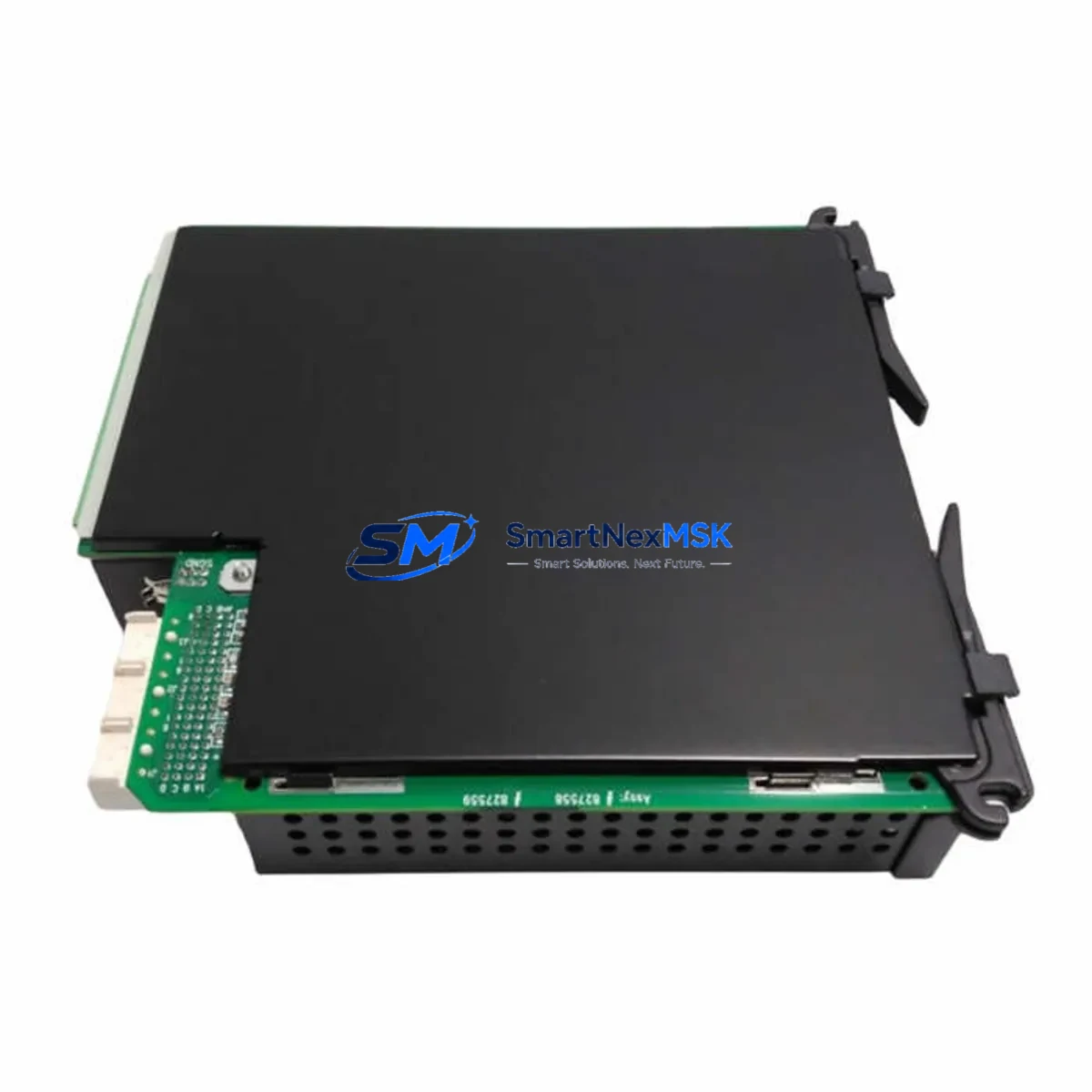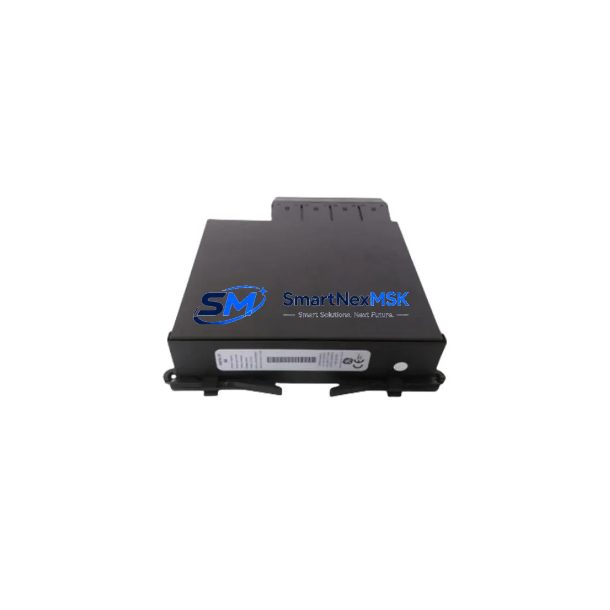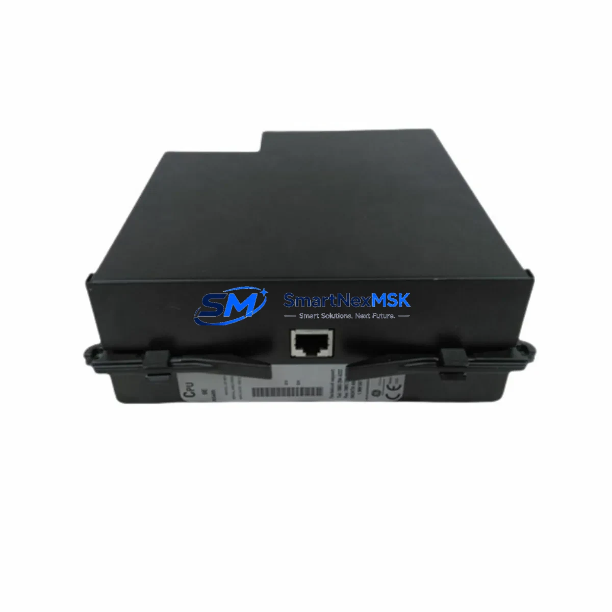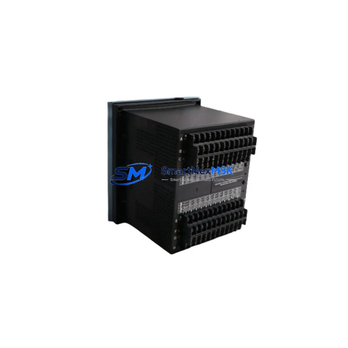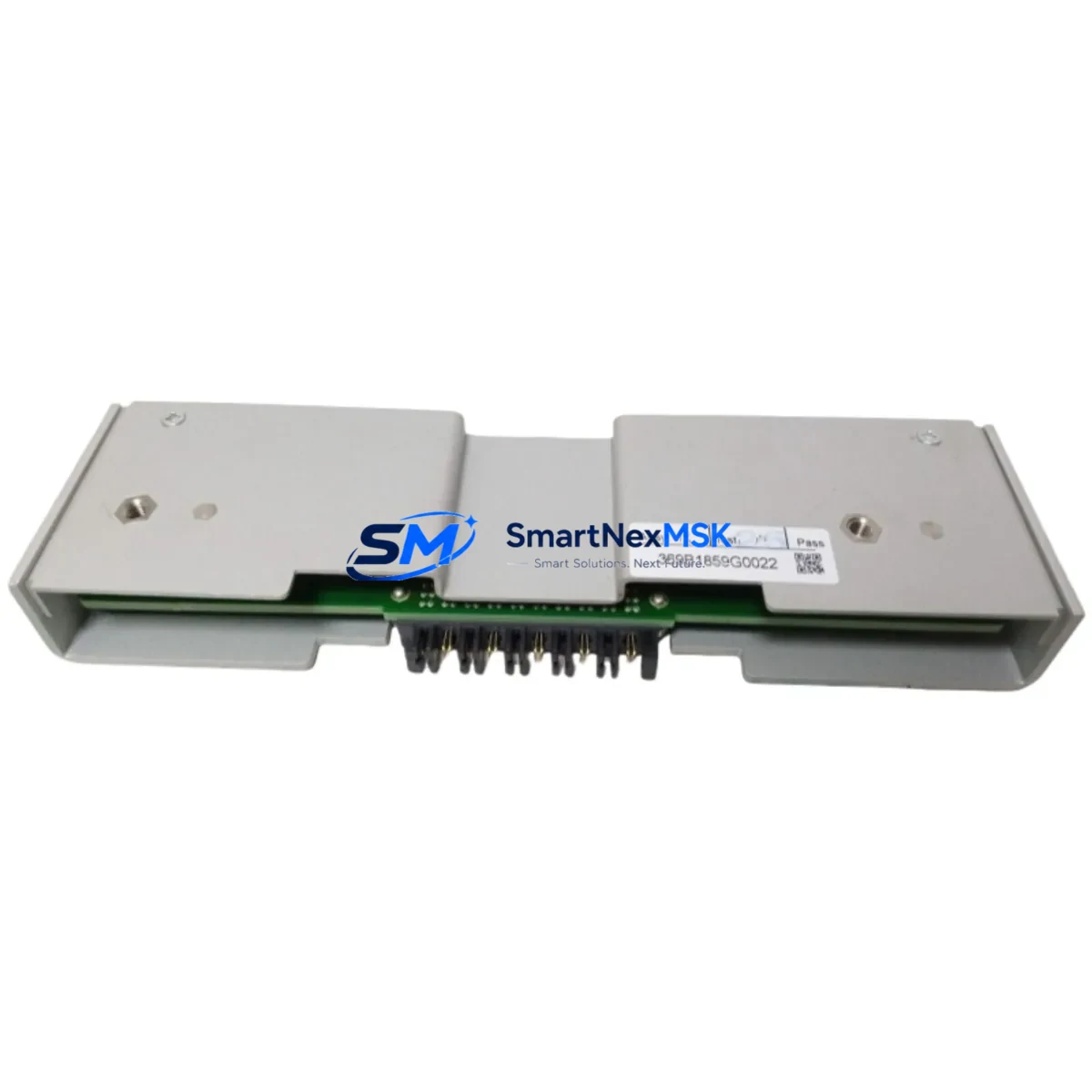
GE BAI11-369B1868G5002 Spare for Multilin 369 Automation: Busbar Protection Replacement & Downtime Risk Control
The GE BAI11-369B1868G5002 is an original spare module for the GE Multilin 369 Motor Management Relay series — a cornerstone protection device widely deployed in industrial motor control centers, switchgear panels, and busbar protection circuits. When this relay reaches end-of-life or fails during operation, rapid replacement with a verified original spare is critical to restoring protection coverage and preventing cascading electrical faults. This listing provides a maintenance-ready, tested unit with a 12-month warranty, designed to support both planned maintenance cycles and emergency breakdown recovery.
For maintenance engineers managing aging motor protection infrastructure, the BAI11-369B1868G5002 represents a direct, drop-in replacement that preserves existing wiring topology, CT/VT ratios, and communication configurations. Procurement engineers sourcing this part for strategic spare inventory will benefit from confirmed OEM compatibility, pre-shipment functional verification, and long-term supply continuity from a dedicated industrial automation parts supplier.
Spare Maintenance Table
| Parameter | Specification / Detail |
|---|---|
| Part Number | BAI11-369B1868G5002 |
| Brand | GE Grid Solutions (GE Multilin) |
| Series | Multilin 369 Motor Management Relay |
| Product Type | Protection Relay / Motor Management Unit |
| Application | Busbar protection, motor overcurrent, thermal overload, ground fault detection |
| Compatibility | GE Multilin 369 Series; compatible with standard 369 relay panel cutouts and wiring harnesses |
| Communication | RS-485 / Modbus RTU (series standard); EnerVista software configurable |
| Mounting | Panel-mount, standard 369 chassis footprint |
| Operating Voltage | Per 369 series specification (AC/DC auxiliary supply, consult nameplate) |
| Operating Temperature | -20°C to +60°C (industrial environment rated) |
| Origin | USA (GE Grid Solutions OEM) |
| Condition | Original spare — new or refurbished-to-spec with full functional test |
| Pre-shipment Test | Yes — energized functional verification prior to dispatch |
| Warranty | 12 Months from date of shipment |
| Lead Time | In-stock: ships within 3–5 business days; ex-stock subject to availability |
| Maintenance Recommendation | Inspect every 12–24 months; replace on trip event or self-diagnostic fault |
Maintenance Planning for Continuous Operation
Replacing the BAI11-369B1868G5002 in a live motor protection panel is rarely an isolated task. A thorough maintenance engineer will treat this relay swap as an opportunity to audit the entire protection circuit. Before energizing the replacement unit, verify the integrity of the current transformer (CT) secondary wiring and confirm CT burden ratings remain within the 369 relay’s input specifications. Check the auxiliary power supply module feeding the relay — a degraded 24 VDC or 120 VAC supply rail is a common root cause of nuisance trips and relay resets that are often misdiagnosed as relay failure.
Inspect the terminal blocks and DIN rail assemblies in the same panel section. Loose or corroded terminals on CT, VT, or control wiring connections can introduce measurement errors that trigger false protection operations. If the panel includes a GE Multilin 750 or 850 feeder protection relay on the same bus section, cross-check its event log for any upstream fault records that may have stressed the 369 relay prior to failure.
For panels using RS-485 Modbus communication, inspect the communication cable shielding and termination resistors. A failed 369 relay that was also a Modbus node may have disrupted the communication chain — verify that adjacent devices such as the GE Multilin SR750 or any connected SCADA gateway are responding correctly after the replacement. If the system uses a GE UR series relay (such as the GE F60 or D60) for differential or distance protection on the same feeder, confirm that inter-relay communication and protection coordination settings remain intact.
Also inspect the panel’s surge protection devices (SPDs) and fuse holders on the relay auxiliary supply circuit. A blown fuse or degraded SPD is often the silent cause behind relay damage in high-transient industrial environments. For older installations, consider replacing the relay’s output contact wiring with appropriately rated control cable to ensure trip coil and alarm circuits meet current insulation standards. Keeping a GE Multilin 369 configuration backup file (via EnerVista software) on the maintenance laptop ensures that relay settings can be restored within minutes of hardware replacement, dramatically reducing mean time to recovery (MTTR).
Site Replacement Workflow
Step 1 — Isolation & Lockout/Tagout: De-energize the motor feeder and apply LOTO to both the main breaker and the relay auxiliary supply. Confirm zero energy state with a calibrated voltage tester before opening the panel.
Step 2 — Configuration Backup: If the existing relay is still partially functional, connect via EnerVista Multilin Setup software and export the full settings file. This preserves CT ratios, protection setpoints, communication addresses, and output relay assignments.
Step 3 — Physical Removal: Disconnect all wiring from the relay terminals in labeled sequence. Remove the relay from the panel cutout. Photograph the wiring layout before disconnection if no wiring diagram is available on-site.
Step 4 — Install BAI11-369B1868G5002: Mount the replacement relay into the existing panel cutout. Reconnect all wiring per the original diagram or photograph. Verify CT polarity and VT phase connections before energizing.
Step 5 — Settings Restore & Commissioning: Upload the saved configuration file via EnerVista. Verify all protection elements, communication parameters, and output relay assignments. Perform a secondary injection test if site conditions permit, or at minimum verify metering accuracy against known load values.
Step 6 — Return to Service: Re-energize the auxiliary supply and confirm relay self-test passes. Re-energize the motor feeder and monitor for any alarm or trip events during the first operational cycle. Document the replacement in the maintenance log with the new relay serial number and warranty start date.
This workflow is applicable whether replacing a failed unit on an emergency basis or executing a planned lifecycle replacement as part of a scheduled outage. The BAI11-369B1868G5002 is a direct form-fit-function replacement for the standard 369 relay chassis, requiring no panel modification and preserving full backward compatibility with existing wiring and communication infrastructure.
Spare Parts Support FAQ
Q1: Is the BAI11-369B1868G5002 a direct replacement for all GE Multilin 369 variants?
The BAI11-369B1868G5002 is designed for the GE Multilin 369 Motor Management Relay platform. Compatibility with specific sub-variants depends on the firmware version and hardware revision of the installed base. We recommend providing your existing relay’s nameplate data (full model number and firmware version) for confirmation before ordering. Our technical team can verify compatibility within one business day.
Q2: What pre-shipment testing is performed on this spare?
Each unit undergoes energized functional verification prior to dispatch, including auxiliary power-up self-test, output relay continuity check, and communication port response verification. A test report is available upon request. Units are packed in anti-static, shock-protected packaging to ensure safe transit to site.
Q3: How should I manage spare inventory for the GE Multilin 369 in a critical facility?
For facilities with three or more 369 relays in service, we recommend maintaining at least one cold-standby spare on-site. Given the relay’s role in motor protection and busbar fault isolation, a spare holding strategy based on MTBF data and criticality classification is advisable. We offer long-term supply agreements and reserved stock programs for customers managing large installed bases of GE Multilin protection relays.
Q4: What is covered under the 12-month warranty?
The 12-month warranty covers manufacturing defects, component failure under normal operating conditions, and any fault attributable to the unit itself (excluding damage from incorrect installation, overvoltage events, or physical mishandling). Warranty claims are processed with a replacement-first policy — a replacement unit is dispatched upon fault confirmation, minimizing site downtime. Warranty period begins from the date of shipment.
© 2026 SMARTNEXMSK. All rights reserved.
Original Source: https://smartnexmsk.com
Contact: [email protected] | +86 18259474341