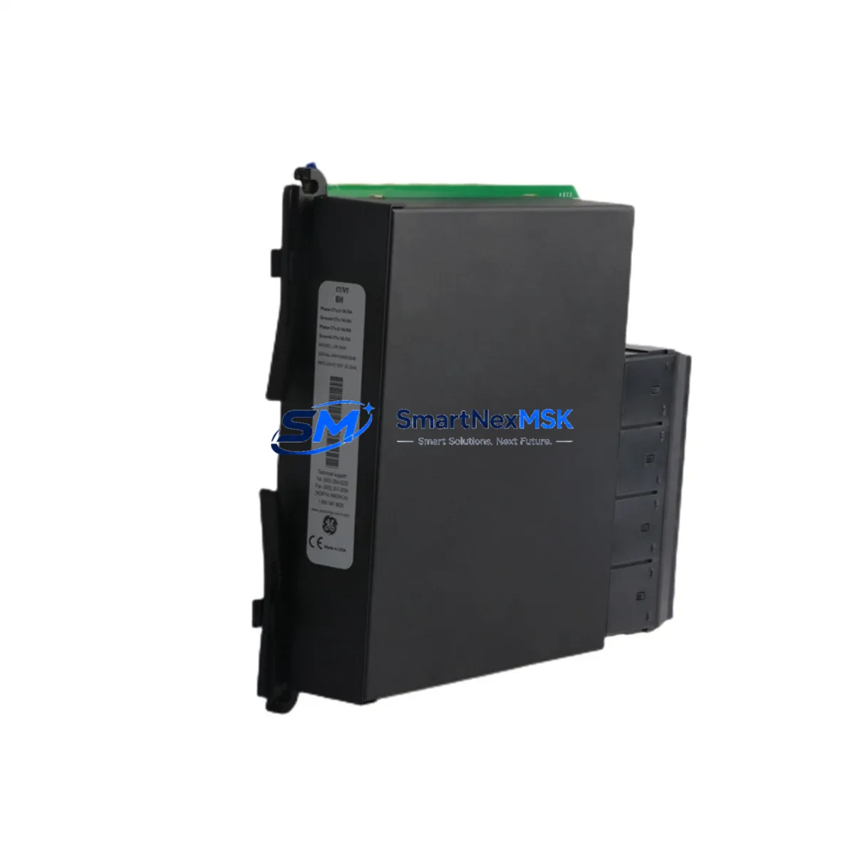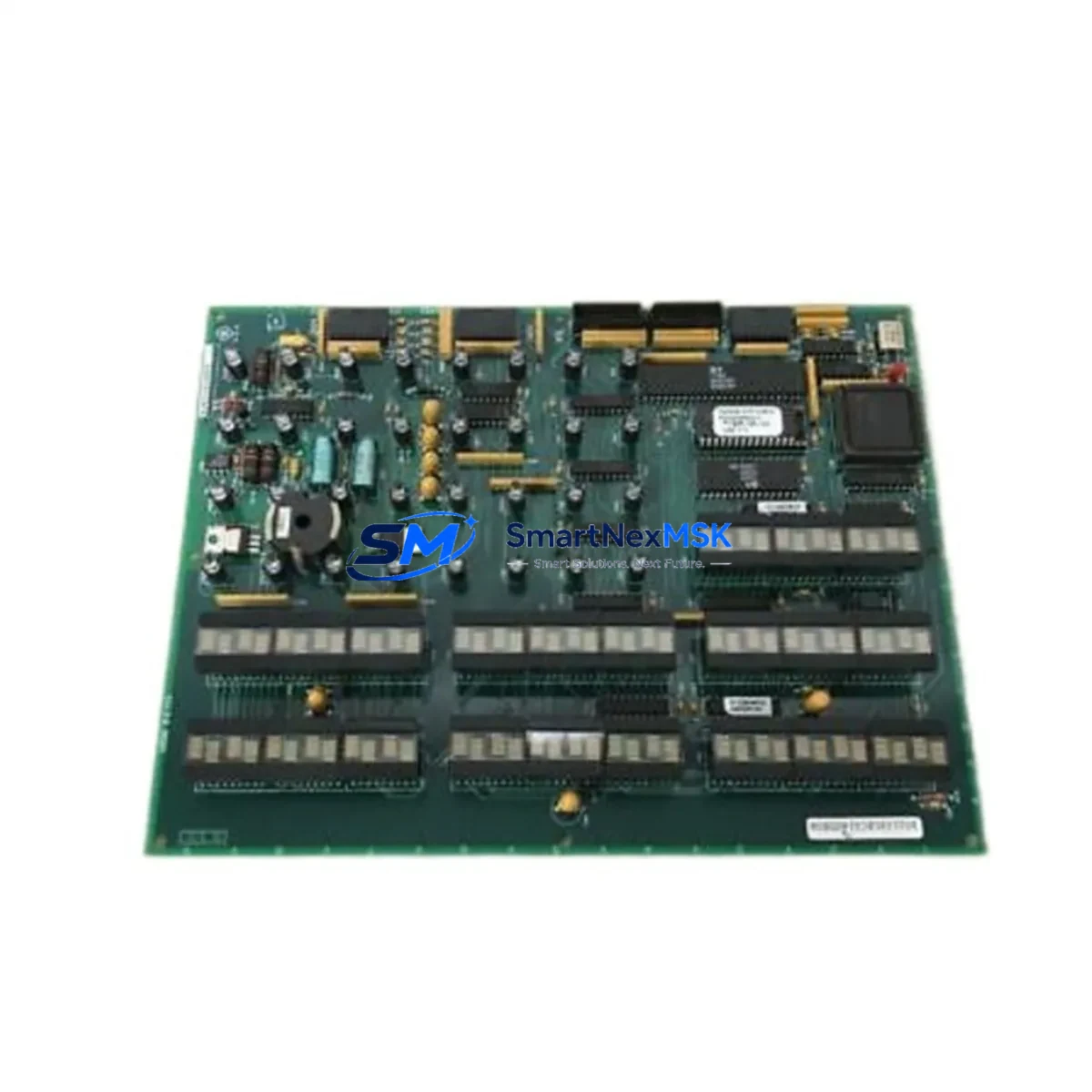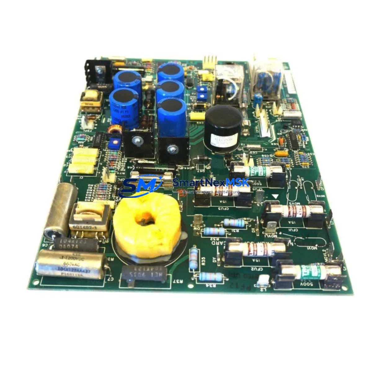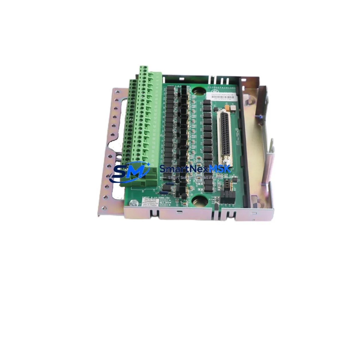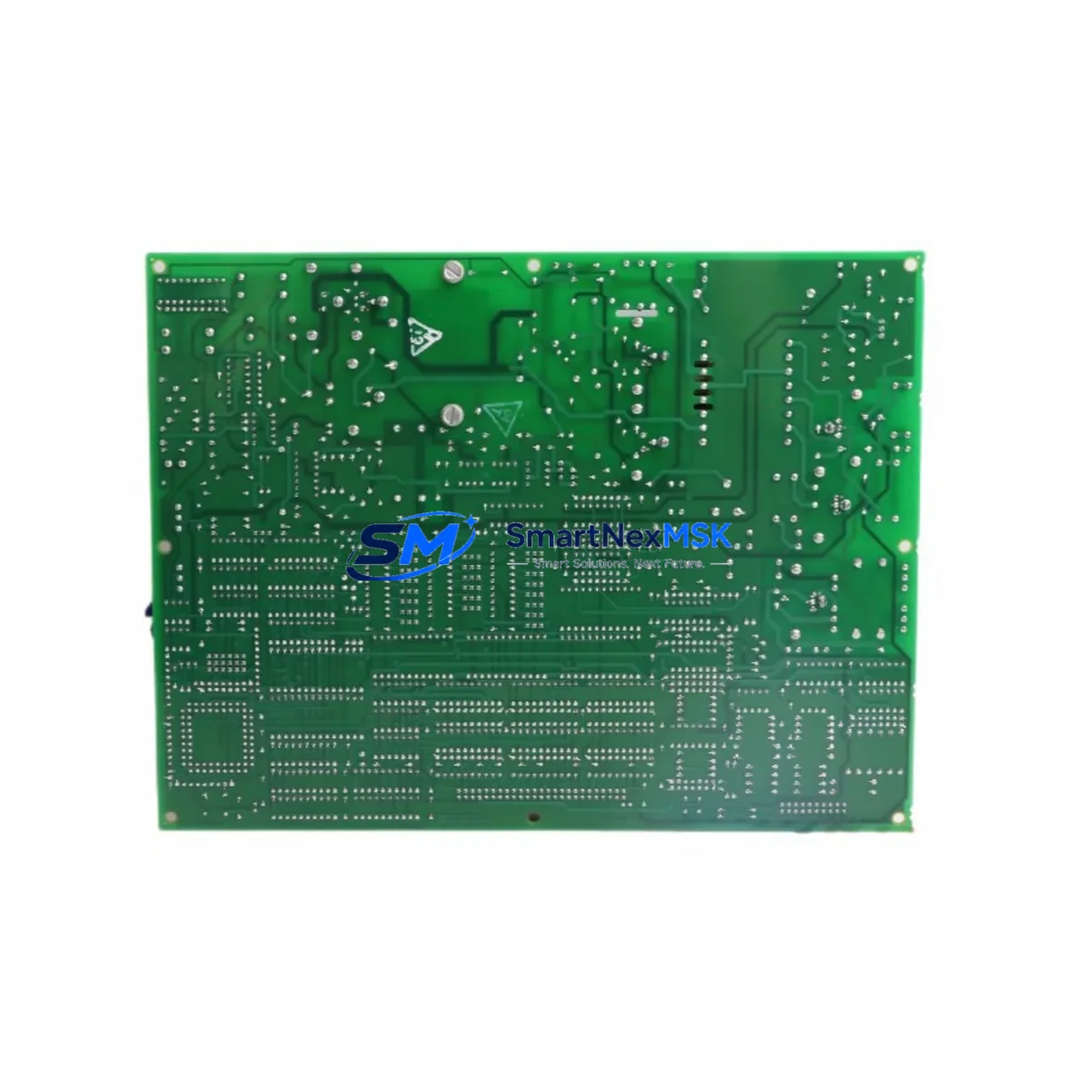
GE DS200TCCAF1ADD Retrofit-Ready Analog I/O Board for Mark V Control Systems
The GE DS200TCCAF1ADD is a high-reliability Analog I/O Board engineered for the GE Mark V Speedtronic turbine control platform. As legacy Mark V installations approach end-of-support milestones, plant engineers and reliability teams are actively sourcing verified replacement boards to sustain operational continuity without committing to a full control system overhaul. The DS200TCCAF1ADD addresses this need directly — offering a drop-in compatible solution that preserves existing terminal wiring, backplane slot assignments, and I/O channel mapping while delivering the signal conditioning performance required for gas turbine, steam turbine, and combined-cycle applications.
This board occupies a defined slot within the Mark V TCCA card cage assembly and interfaces directly with the DS200TCQAG1B Quad Core Processor and the DS200SDCIG2A Signal Distribution Card. During retrofit planning, engineers must verify the backplane connector alignment, confirm the module address DIP switch settings match the original board configuration, and validate that the analog signal ranges — typically 4–20 mA or 0–10 V DC — are correctly scaled within the Mark V Toolbox software environment. Failure to replicate the original address and scaling parameters will result in I/O faults at startup and may trigger turbine trip sequences.
Terminal block wiring should be documented and photographed prior to board removal. The DS200TCCAF1ADD uses a standard 64-pin DIN rail terminal interface consistent with other Mark V I/O boards, including the DS200TBCBG1A Terminal Board. Technicians migrating from a failed or obsolete board should cross-reference the original wiring diagram against the replacement board’s channel assignments to confirm polarity, shielding continuity, and ground reference integrity before energizing the rack.
Upgrade Compatibility Table
| Parameter | Details |
|---|---|
| Compatible Platform | GE Mark V Speedtronic Turbine Control System |
| Board Function | Analog I/O Signal Conditioning and Distribution |
| Backplane Interface | 64-pin DIN, TCCA Card Cage Slot |
| Signal Range | 4–20 mA / 0–10 V DC (configurable per channel) |
| Communication Compatibility | Mark V internal ARCNET / IONet bus |
| Direct Replacement For | DS200TCCAF1ADD (same revision), DS200TCCAF1A variants |
| Installation Requirement | Match DIP switch address; verify Toolbox I/O scaling |
| Retrofit Recommendation | Retain original terminal board; swap board only |
| Commissioning Focus | I/O channel calibration, loop check, HMI tag verification |
| Warranty | 12 Months — Covers manufacturing defects and functional failure |
Retrofit Planning for Existing Automation Systems
A successful DS200TCCAF1ADD retrofit begins well before the board arrives on site. The Mark V control cabinet typically houses multiple interdependent boards that must remain operational during a single-board swap. The DS200TCQAG1B Quad Core Processor continues to execute control logic during the swap window, provided the replacement board is installed within the allowable hot-swap interval defined in the Mark V maintenance manual. If the system does not support hot-swap for this slot, a controlled shutdown sequence must be initiated using the Mark V Toolbox operator interface.
Power supply integrity is a prerequisite for any analog board replacement. The Mark V cabinet is typically fed by a DS200PCCAG1A Power Supply Board that distributes +5 V, ±15 V, and +28 V rails to the card cage. Before installing the DS200TCCAF1ADD, verify that all supply rails are within tolerance using a calibrated multimeter. An out-of-tolerance power rail — particularly the ±15 V analog supply — will cause immediate signal errors on the replacement board and may be misdiagnosed as a board fault.
Communication continuity is maintained through the Mark V’s internal IONet and ARCNET bus architecture. The DS200TCCAF1ADD does not require independent communication configuration; it inherits its network identity from the slot address set via onboard DIP switches. However, if the system includes a DS200SLCCG3A Serial Link Communication Card for Modbus or PROFIBUS integration, the technician should confirm that the analog I/O tags mapped through this card are not disrupted during the board swap. HMI screens built on Cimplicity or third-party SCADA platforms should be monitored for tag loss alarms during the transition.
For plants upgrading from Mark V to Mark VIe, the DS200TCCAF1ADD may serve as an interim solution while the full migration is planned. The Mark VIe platform uses a different I/O architecture based on the IS420ESWBH3A Ethernet Switch and distributed I/O packs, but the analog signal wiring from field instruments can often be reused with appropriate marshalling changes. During this transition period, maintaining a functional Mark V analog I/O layer — anchored by boards like the DS200TCCAF1ADD — reduces the risk of unplanned outages while the new control logic is validated in parallel.
I/O expansion requirements should also be assessed during retrofit planning. If the existing Mark V rack is at capacity, engineers may need to evaluate the DS200IOCAG1A I/O Controller Board to manage additional analog channels without adding a second cabinet. All expansion decisions should be documented in the system’s as-built drawings before commissioning begins.
Downtime Control During System Migration
Minimizing turbine downtime during a DS200TCCAF1ADD replacement requires a structured pre-outage preparation protocol. The original board’s configuration — including DIP switch positions, jumper settings, and Toolbox I/O scaling parameters — must be fully documented before removal. A configuration export from the Mark V Toolbox should be saved to an offline backup location, ensuring that the replacement board can be validated against the known-good configuration without relying on memory or field notes alone.
The physical swap itself typically takes 15–30 minutes for a trained technician familiar with the Mark V card cage. The majority of the outage window is consumed by post-installation verification: loop checks on each analog channel, confirmation of HMI tag values against field instrument readings, and review of the Mark V diagnostic display for any active I/O fault codes. A pre-prepared loop check sheet — listing each channel’s expected engineering unit value and acceptable tolerance — significantly accelerates this phase and reduces the risk of returning the unit to service with an undetected signal error.
Where plant operations permit, a staged restart sequence should be used: energize the replacement board, confirm all analog inputs are reading correctly in the Toolbox, then release the turbine to auto-start mode. This sequence preserves the original control logic without requiring any program modifications and ensures that the HMI operator interface reflects accurate process values from the first moment of operation. All pre-outage and post-outage readings should be logged and retained as part of the plant’s maintenance record for the 12-month warranty period.
Retrofit Support FAQ
Q: Is the DS200TCCAF1ADD a direct drop-in replacement for all Mark V TCCA slot positions?
A: Yes, provided the DIP switch address on the replacement board is set to match the original board’s slot assignment. The DS200TCCAF1ADD is physically and electrically compatible with all standard TCCA card cage positions in the Mark V platform. No backplane modifications are required.
Q: What wiring changes are needed when installing the replacement board?
A: In most cases, no wiring changes are required. The DS200TCCAF1ADD connects to the existing DS200TBCBG1A Terminal Board, which remains in place during the swap. Technicians should verify terminal screw torque and inspect for any corroded or loose connections before reinstalling the terminal board cover.
Q: How is the replacement board tested before shipment?
A: Each DS200TCCAF1ADD unit undergoes functional testing on a live Mark V test rack prior to shipment. Analog channel linearity, signal conditioning accuracy, and backplane communication are verified against GE factory specifications. A test report is available upon request and accompanies units shipped under the 12-month warranty program.
Q: What does the 12-month warranty cover?
A: The warranty covers all manufacturing defects and functional failures under normal operating conditions. It does not cover damage resulting from incorrect installation, overvoltage events, or physical mishandling. Warranty claims are processed within 5 business days of receipt of the returned unit, with a replacement board dispatched immediately upon fault confirmation.
© 2026 SMARTNEXMSK. All rights reserved.
Original Source: https://smartnexmsk.com
Contact: [email protected] | +86 18259474341