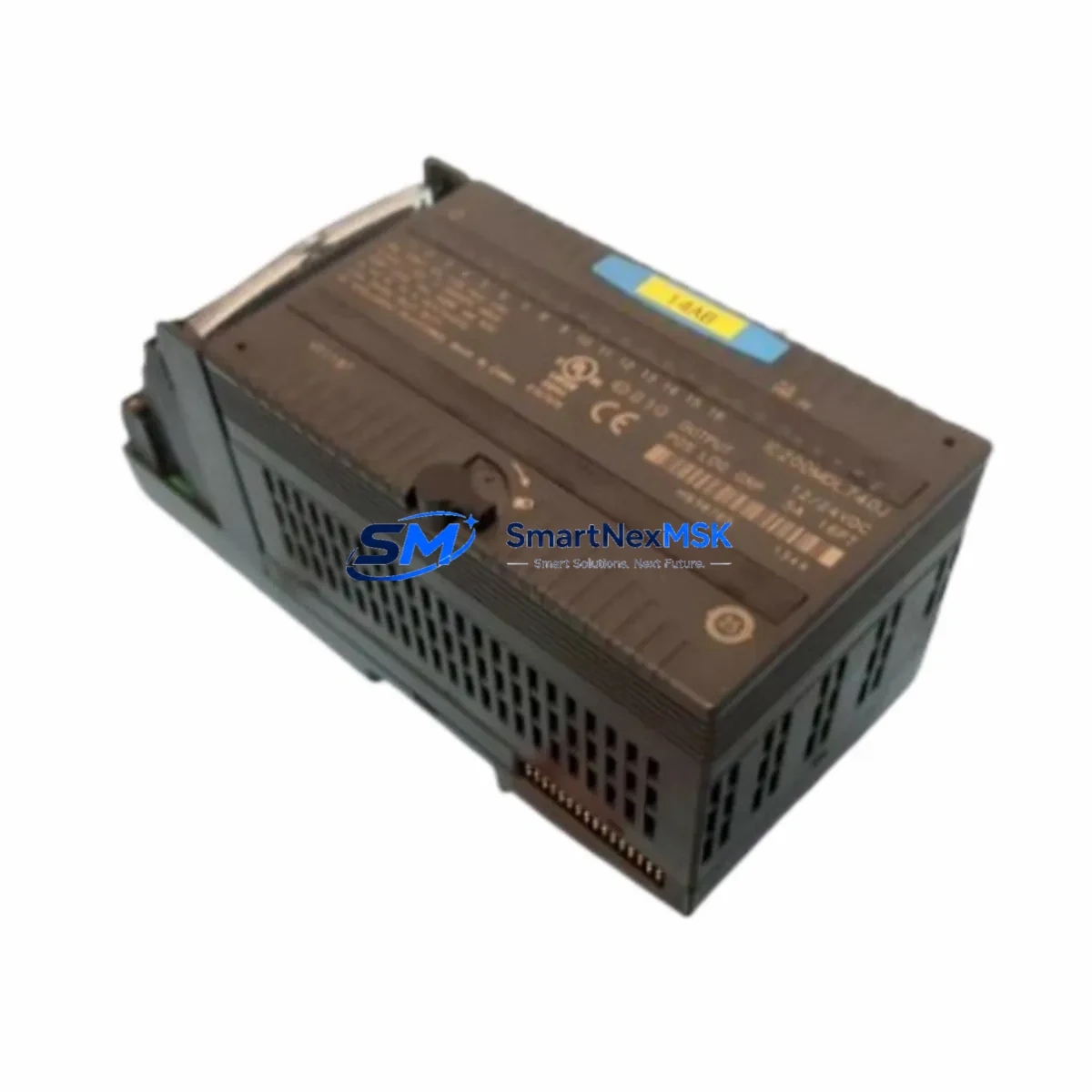
GE IC200MDL740J Maintenance-Ready Spare for VersaMax Automation
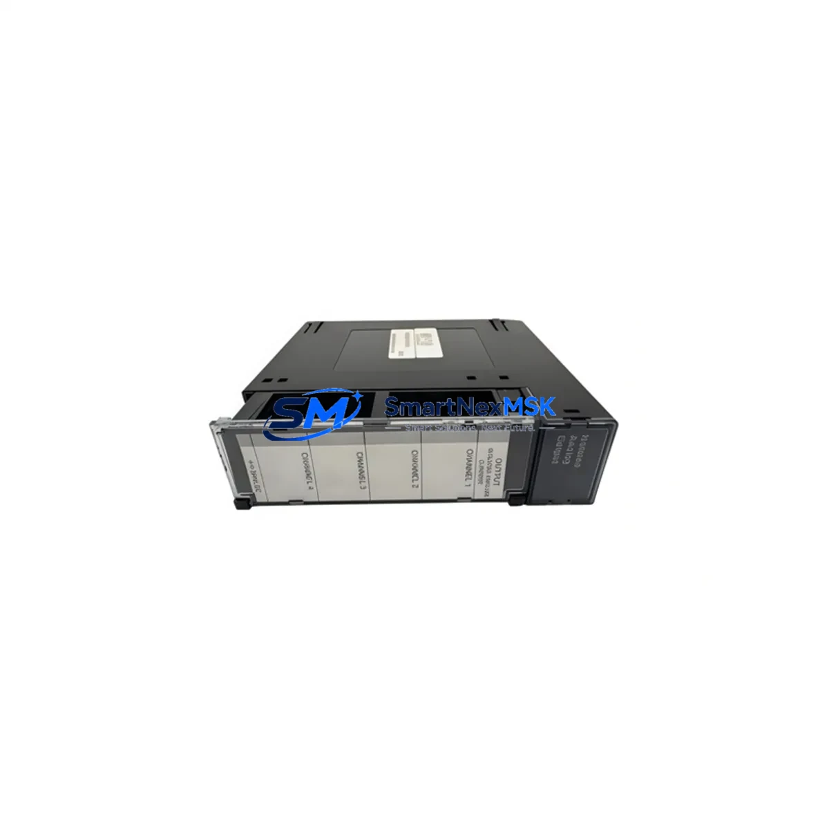
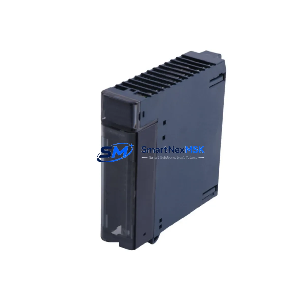
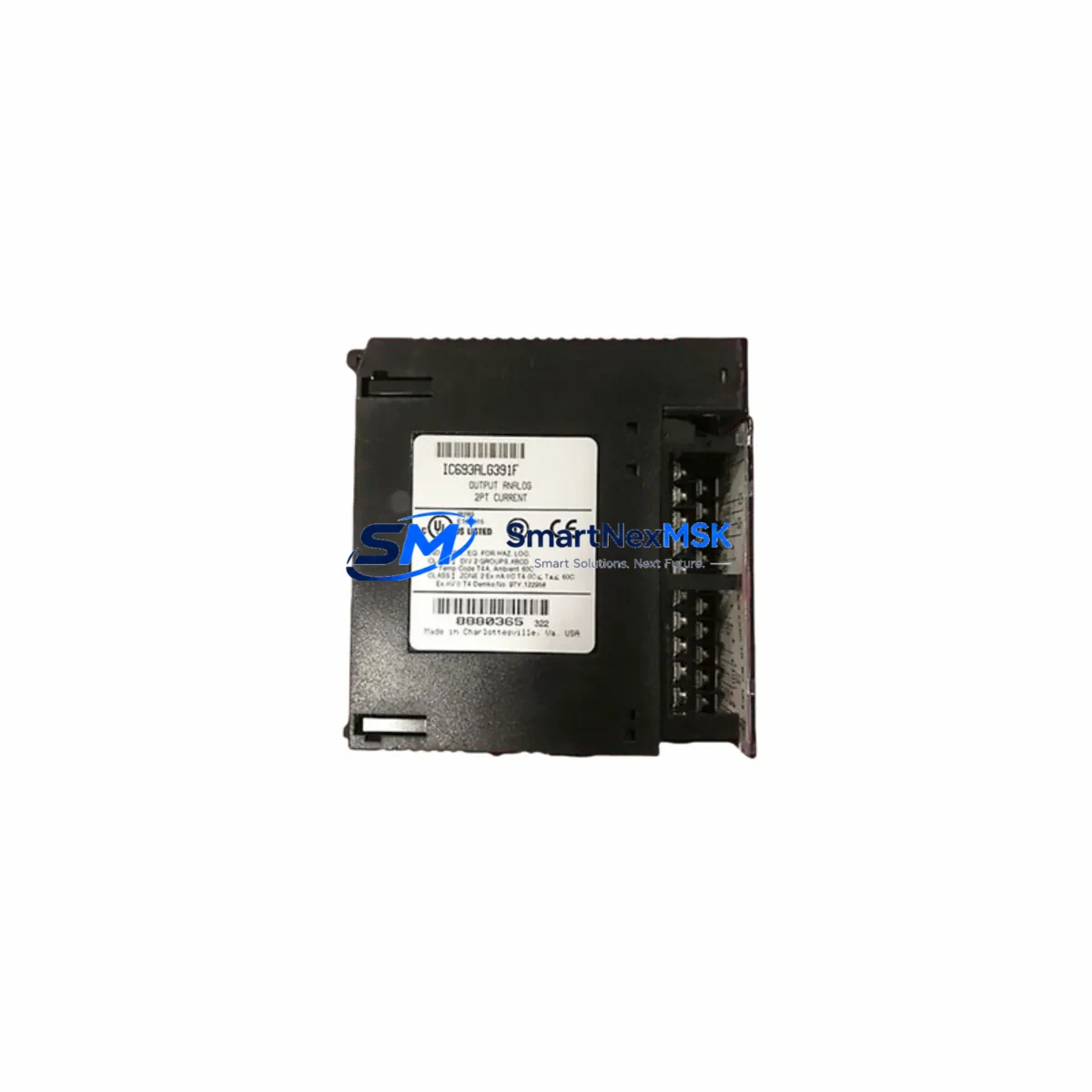
The GE IC200MDL740J is a 16-point, 120VAC discrete output module designed for the GE VersaMax I/O system — one of the most widely deployed modular I/O platforms in North American industrial automation. As a maintenance-ready original spare, the IC200MDL740J is engineered to deliver direct drop-in replacement capability for aging or failed output modules in active production environments, minimizing unplanned downtime and restoring control system integrity without requiring hardware reconfiguration or software re-mapping.
For maintenance engineers managing legacy VersaMax installations, sourcing a verified original IC200MDL740J is critical. Counterfeit or incompatible substitutes risk output signal mismatch, blown fuses, or PLC fault codes that extend downtime far beyond the initial failure window. SMARTNEXMSK supplies only original, tested units with full functional verification prior to shipment, backed by a 12-month warranty covering manufacturing defects and operational failures under normal industrial use conditions.
Spare Maintenance Table
| Part Number | IC200MDL740J |
| Brand / Manufacturer | GE Fanuc Automation (now Emerson / Proficy) |
| Series | VersaMax Modular I/O |
| Module Type | Discrete Output Module |
| Output Points | 16-point |
| Output Voltage | 120VAC |
| Output Type | Triac (solid-state AC output) |
| Load Current per Point | 0.5A (typical) |
| Backplane Compatibility | VersaMax I/O Carrier / Backplane (IC200CHS series) |
| Communication Interface | Via VersaMax NIU or CPU carrier |
| Operating Temperature | 0°C to 60°C |
| Mounting | DIN rail via VersaMax carrier |
| Isolation | Optical isolation between field and logic side |
| Indicator LEDs | Per-point output status LEDs |
| Application Environment | Industrial control panels, machine automation, process control |
| Maintenance Recommendation | Inspect triac outputs annually; verify LED status under load; check carrier seating |
| Warranty | 12 Months — covers manufacturing defects and functional failures |
| Condition | Original, tested before shipment |
Maintenance Planning for Continuous Operation
When replacing the IC200MDL740J in a VersaMax I/O rack, a disciplined maintenance engineer will treat the module swap as an opportunity to audit the surrounding electrical environment. Output module failures in 120VAC discrete circuits are rarely isolated events — they are often preceded or accompanied by stress on adjacent components.
Begin by inspecting the IC200CHS022 or IC200CHS014 carrier backplane for cracked connectors, oxidized contacts, or mechanical damage from repeated module insertions. A degraded carrier can cause intermittent output faults even after a new IC200MDL740J is installed. Next, verify the IC200PWR002 or equivalent VersaMax power supply module is delivering stable 24VDC logic power within specification — voltage sag under load is a common root cause of output module triac stress.
On the field wiring side, inspect the terminal block assemblies and field-side fusing. Each 120VAC output channel should be protected by an appropriately rated fuse (typically 0.5A–1A fast-blow); blown fuses on multiple channels indicate an upstream load fault that must be resolved before the replacement module is energized. Check signal isolation barriers if the output circuit interfaces with instrumentation loops — a failed isolator can inject noise that mimics output module failure.
For systems using a VersaMax Network Interface Unit (NIU) such as the IC200BEM003 (Profibus) or IC200PBI001 (DeviceNet), confirm that the NIU firmware and I/O configuration table still correctly maps the output module slot after replacement. Slot reassignment errors are a common commissioning mistake after emergency swaps. If the VersaMax rack communicates upstream to a GE Series 90-30 PLC (IC693 series) or a PACSystems RX3i controller, verify the I/O configuration in Proficy Machine Edition matches the physical rack layout.
Additionally, inspect any IC200MDL650 or IC200MDL660 discrete input modules in the same rack — input modules sharing the same backplane segment can be affected by power transients caused by a failing output module. Relay output modules such as the IC200MDL930 in adjacent slots should also be checked for contact wear if they share the same load circuit. Finally, review the HMI alarm history (whether on a QuickPanel, iFIX SCADA node, or third-party panel) for recurring output fault codes in the weeks preceding the failure — this data is invaluable for root cause analysis and future spare parts planning.
Site Replacement Workflow
The IC200MDL740J is designed for tool-free module replacement within the VersaMax carrier system, making it one of the fastest field-swappable output modules in its class. Follow this workflow to minimize downtime and ensure system compatibility:
Step 1 — Isolate and de-energize: Switch the affected output group to a safe state via the PLC program (force outputs OFF) before physically removing the module. Do not rely solely on the control panel E-stop — confirm output LED indicators are extinguished.
Step 2 — Document slot position: Photograph or record the slot number within the VersaMax carrier. Slot position determines the I/O address mapping in the PLC configuration. Incorrect reinstallation in an adjacent slot will cause address conflicts and PLC faults.
Step 3 — Remove and inspect: Extract the failed IC200MDL740J and inspect the carrier connector pins for damage or contamination. Clean with isopropyl alcohol if necessary before inserting the replacement unit.
Step 4 — Insert replacement: Seat the new IC200MDL740J firmly until the locking tab engages. Re-energize the power supply and observe the module’s status LEDs — all output LEDs should be OFF (outputs de-energized) and no fault LED should be illuminated.
Step 5 — Functional verification: From the PLC or HMI, force each of the 16 output points ON individually and verify field-side response (actuator movement, indicator lamp, or relay closure). Log the test results as part of the maintenance record.
This workflow is compatible with both hot-swap-capable VersaMax configurations and standard power-down replacement procedures, depending on the NIU type and system safety requirements. For legacy systems where the VersaMax rack has been in service for 10+ years, this replacement is also an opportunity to evaluate whether a full rack refresh with current-generation VersaMax or PACSystems I/O is warranted as part of a long-term system life extension strategy.
Spare Parts Support FAQ
Q1: Is the IC200MDL740J still in production, and how long can I source it?
The IC200MDL740J has reached end-of-active-production by GE/Emerson, but SMARTNEXMSK maintains long-term inventory of original units to support installed base maintenance. We specialize in sustaining supply for discontinued and legacy automation components, ensuring your VersaMax system can remain operational without forced migration. Contact us for volume pricing and long-term supply agreements.
Q2: How do I verify compatibility before installation?
The IC200MDL740J is compatible with all standard VersaMax I/O carriers (IC200CHS series) and is recognized by VersaMax NIUs and GE PACSystems/Series 90 CPUs without firmware changes. Confirm your carrier part number and NIU model before ordering. Our technical team can assist with compatibility verification based on your rack configuration and PLC model.
Q3: What pre-shipment testing is performed on each unit?
Every IC200MDL740J shipped by SMARTNEXMSK undergoes functional output testing — each of the 16 output channels is verified for correct switching response and optical isolation integrity. Units are inspected for physical damage, connector condition, and LED functionality. A test report is available upon request for quality-critical applications.
Q4: What does the 12-month warranty cover?
Our 12-month warranty covers manufacturing defects and functional failures under normal industrial operating conditions. If the IC200MDL740J fails within 12 months of shipment due to a verified product defect, we will provide a replacement unit or full refund. Warranty claims require failure documentation; our support team will guide you through the process with minimal administrative burden.
© 2026 SMARTNEXMSK. All rights reserved.
Original Source: https://smartnexmsk.com
Contact: [email protected] | +86 18259474341