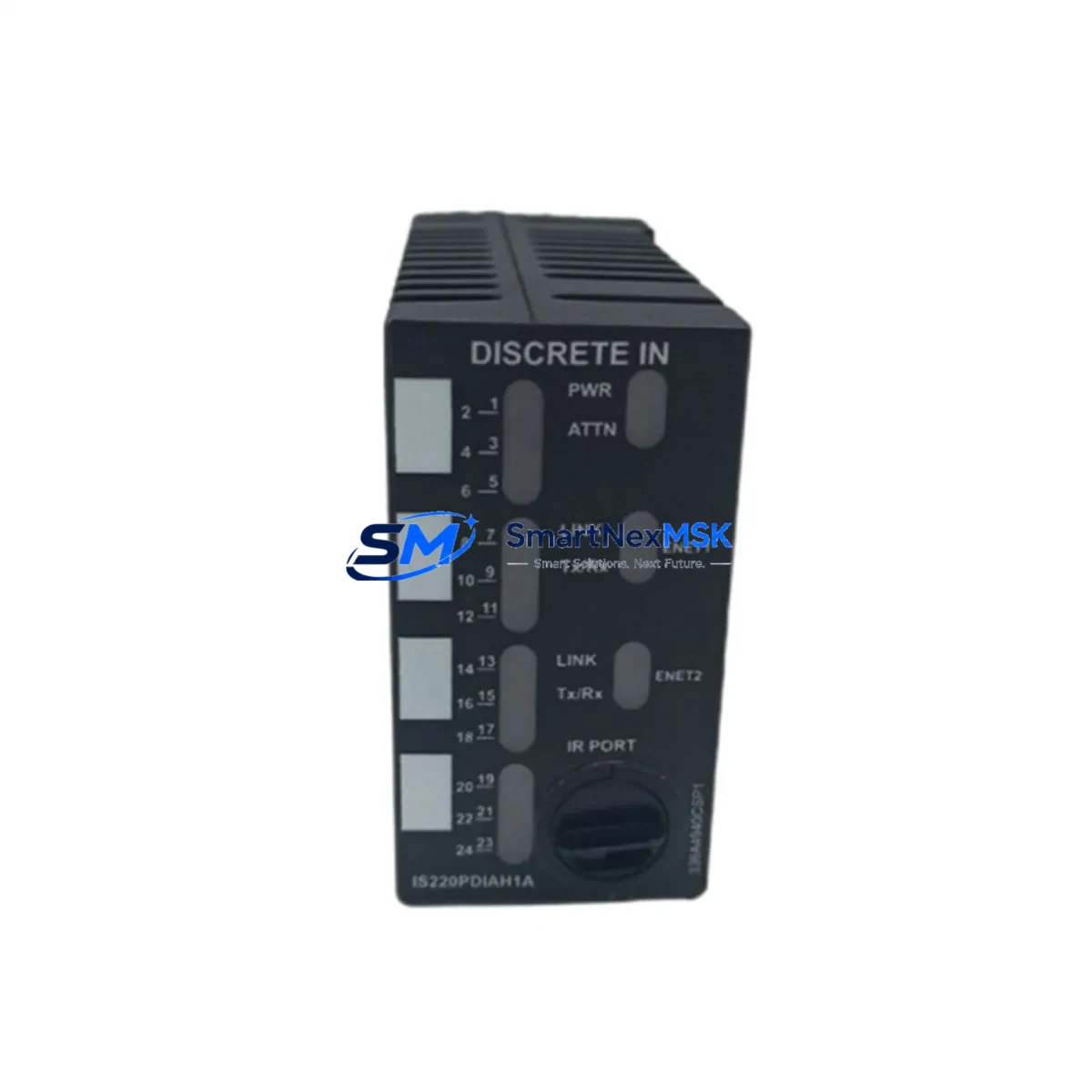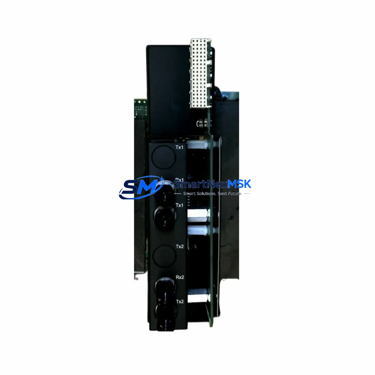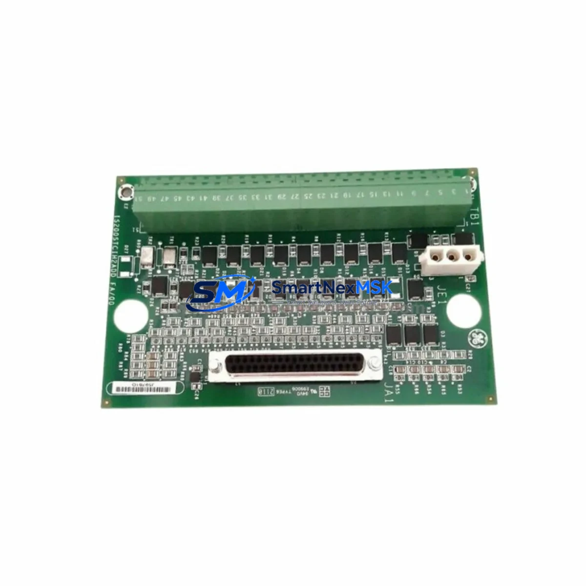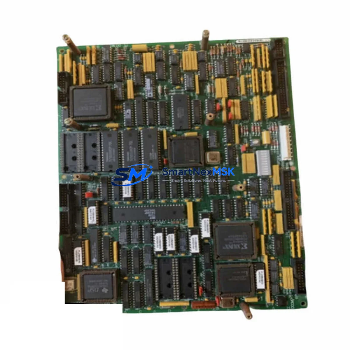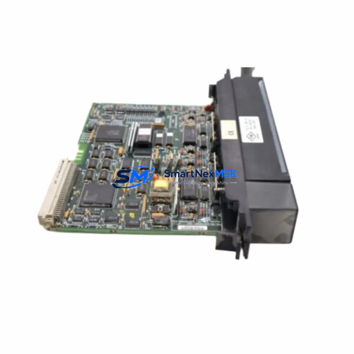
GE IC697ALG320 Retrofit-Ready Analog Output Module for Series 90-70 Control Systems
The GE IC697ALG320 is an 8-channel analog output module engineered for the GE Series 90-70 PLC platform — one of the most widely deployed distributed control architectures in heavy industry, power generation, and process manufacturing. As GE Fanuc has transitioned its automation portfolio, the IC697ALG320 has become a critical retrofit and replacement component for facilities operating legacy Series 90-70 control cabinets that cannot justify a full system migration. This module delivers 4–20 mA or 0–10 V DC analog output signals across eight independently configurable channels, maintaining full backward compatibility with the IC697 backplane and rack architecture.
Whether you are replacing a failed output module on a running production line, upgrading a control cabinet to extend its operational life by 5–10 years, or migrating I/O capacity from an older IC697ALG320A revision, this module is stocked, tested, and ready to ship with a 12-month warranty covering both hardware and firmware integrity.
Upgrade Compatibility Table
| Parameter | IC697ALG320 Specification | Retrofit / Replacement Notes |
|---|---|---|
| Output Channels | 8 channels (4–20 mA / 0–10 V DC) | Direct replacement for IC697ALG320A; channel mapping preserved |
| Backplane Interface | Series 90-70 VME-based backplane | Compatible with IC697CHS750, IC697CHS782, IC697CHS790 racks |
| Power Consumption | +5 VDC @ 0.5 A; +24 VDC field power required | Verify IC697PWR711 or IC697PWR724 power supply capacity before installation |
| Module Address | Configured via Logicmaster 90 or Proficy Machine Edition | Re-use existing %AQ address block; no re-addressing required if slot position is unchanged |
| Communication Protocol | Backplane parallel I/O bus (non-networked) | No protocol migration needed; CPU IC697CPU772 or IC697CPU781 compatible |
| Terminal Wiring | 36-pin field terminal block (IC697ACC724) | Existing field wiring reusable; verify terminal torque spec (0.5 N·m) |
| HMI Compatibility | CIMPLICITY, iFIX, or third-party OPC-DA/UA via IC697CMM742 | No HMI screen changes required if tag names are preserved |
| Firmware / Configuration | Hardware-configured; no firmware flashing required | Restore configuration from existing Logicmaster or PME project backup |
| Warranty | 12-Month Warranty — covers hardware defects, channel calibration drift, and backplane connector integrity | |
Retrofit Planning for Existing Automation Systems
Replacing the IC697ALG320 in an active control system requires a structured approach to avoid unplanned downtime and configuration loss. Begin by auditing the existing rack layout: confirm the slot position of the failed module within the IC697CHS750 or IC697CHS782 chassis, and document the %AQ address assignments currently mapped in the CPU program. The IC697CPU772 or IC697CPU781 controller will retain its program in battery-backed RAM during a hot-swap procedure if the rack supports it, but a full program backup to the programming terminal via Logicmaster 90 or Proficy Machine Edition is mandatory before any physical intervention.
Field wiring connected to the IC697ACC724 terminal block should be photographed and labeled before disconnection. The 36-pin terminal block is removable without disturbing field cables, which significantly reduces reconnection time. Verify that the IC697PWR711 or IC697PWR724 power supply can sustain the additional +24 VDC field power demand if you are adding channels that were previously unused. In multi-rack configurations using the IC697BEM731 bus expansion module, confirm that the remote rack’s power budget is not exceeded after module replacement.
For facilities running Ethernet-connected SCADA systems through the IC697CMM742 communications module or a dedicated IC697CMM711 Ethernet interface, no network reconfiguration is required — the analog output data is presented to the CPU as standard %AQ registers, and the SCADA tag database remains unchanged. If the plant uses a GE Series 90-30 controller (IC693 platform) in a parallel control zone, note that the IC697ALG320 is not cross-compatible with IC693 racks; separate IC693ALG392 or IC693ALG442 modules serve that platform.
Where the retrofit involves migrating from an older IC697ALG320A revision to the current IC697ALG320, verify the output range jumper configuration on the module’s PCB. Both revisions support identical field wiring, but the internal range selection jumpers may differ. Our pre-shipment testing protocol validates all 8 channels at both 4–20 mA and 0–10 V DC ranges before dispatch, and a calibration certificate is included with each unit.
Downtime Control During System Migration
Minimizing production downtime during an IC697ALG320 replacement is achievable with the right preparation. The most effective strategy is a pre-staged swap: configure and bench-test the replacement module before the maintenance window, confirm channel output values match the process setpoints documented in the control narrative, and prepare a rollback plan using the original module if the replacement does not initialize correctly within the first 15 minutes of commissioning.
For continuous-process industries where even a brief output interruption is unacceptable, consider placing the affected analog output channels in manual control at the DCS or HMI level before the swap. CIMPLICITY or iFIX operator stations can hold the last output value while the module is physically replaced, provided the CPU is in RUN-with-I/O-disabled mode during the swap window. After reinserting the IC697ALG320 and restoring the terminal block, bring the CPU back to full RUN mode and verify each channel’s output against the process instrument reading before releasing control back to automatic.
Document the entire procedure in the plant’s maintenance management system, including the module serial number, slot position, rack ID, and post-installation calibration check results. This record supports future audits and reduces diagnostic time if a related fault occurs within the 12-month warranty period. Our technical team is available to support remote commissioning verification via email or video call at no additional charge.
Retrofit Support FAQ
Q1: Is the IC697ALG320 a direct drop-in replacement for the IC697ALG320A?
Yes. The IC697ALG320 is backward compatible with the IC697ALG320A in terms of backplane pinout, %AQ address mapping, and field terminal block (IC697ACC724). The only difference is an internal PCB revision that improves channel isolation. No program changes are required.
Q2: What pre-shipment testing is performed on each unit?
Every IC697ALG320 unit undergoes a full 8-channel functional test at both 4–20 mA and 0–10 V DC output ranges, backplane communication verification, and a 48-hour burn-in cycle. A test report and calibration certificate are included in the shipment. The 12-month warranty covers any channel drift or hardware failure identified after installation.
Q3: Can this module be used in a Series 90-70 rack alongside IC697MDL340 discrete input modules and IC697MDL940 relay output modules?
Yes. The IC697ALG320 occupies a single slot in any IC697CHS750, IC697CHS782, or IC697CHS790 rack and coexists with all standard Series 90-70 discrete and analog I/O modules. Slot assignment is flexible; the CPU automatically identifies the module type during power-up configuration scan.
Q4: What should I verify regarding wiring compatibility before installation?
Confirm that the existing field cables are rated for the signal type (current loop or voltage) configured on each channel. Check that the IC697ACC724 terminal block screws are torqued to 0.5 N·m and that shielded cable is used for runs exceeding 10 meters to prevent signal noise. If the installation environment has high EMI (near VFDs or large contactors), verify that cable shields are grounded at a single point at the control cabinet end only.
© 2026 SMARTNEXMSK. All rights reserved.
Original Source: https://smartnexmsk.com
Contact: [email protected] | +86 18259474341