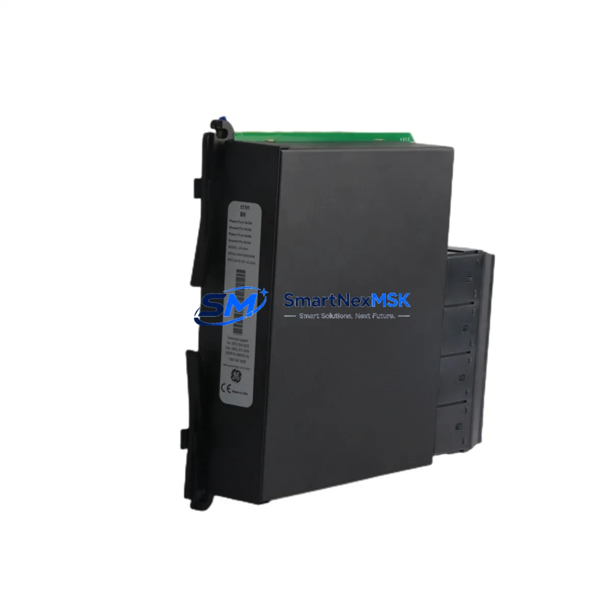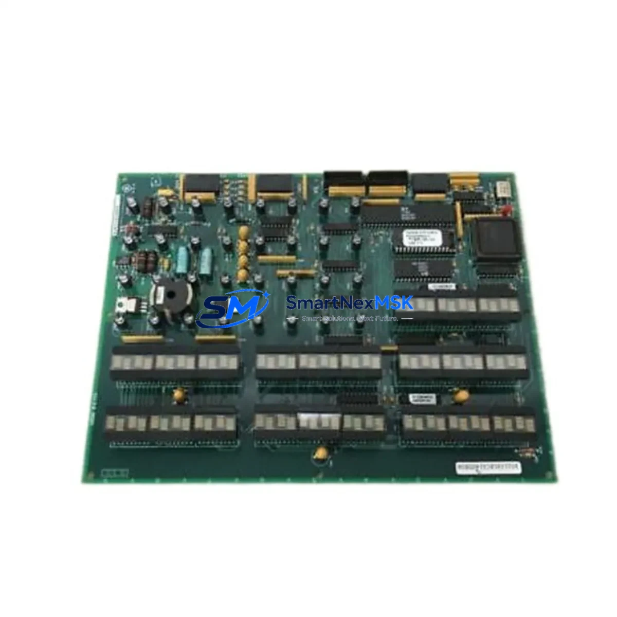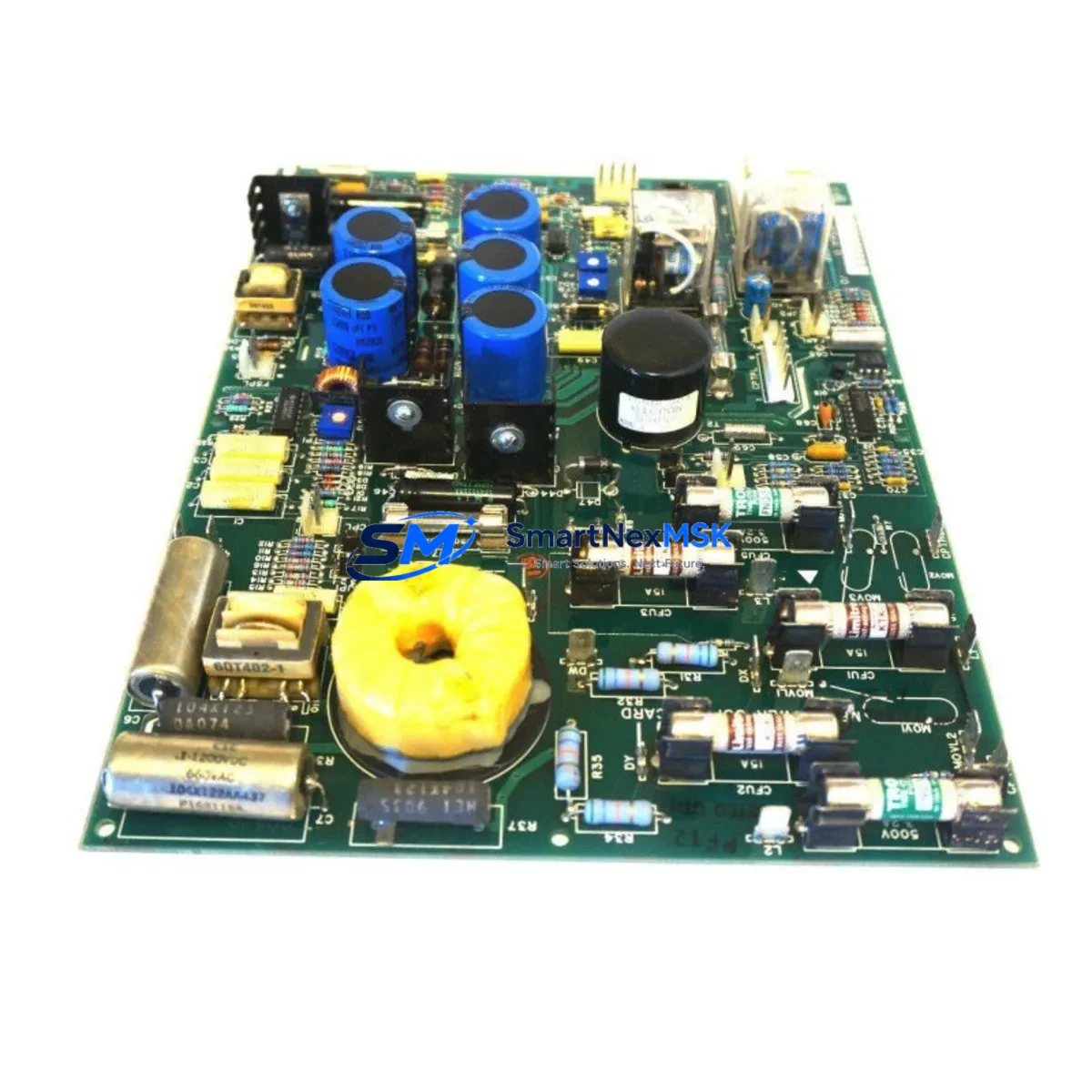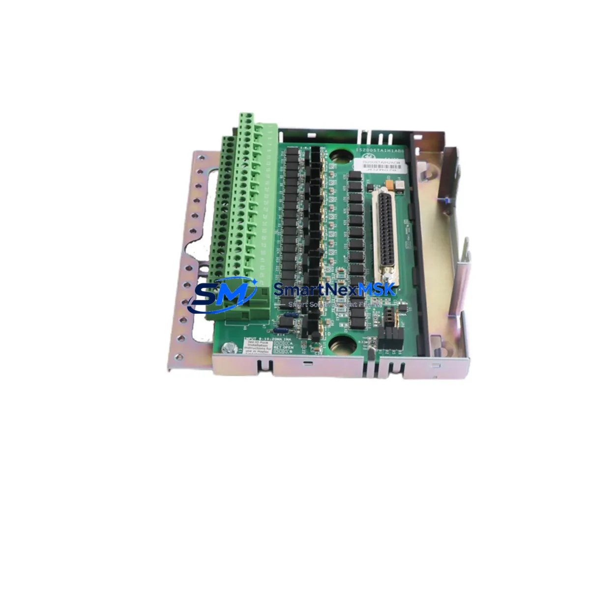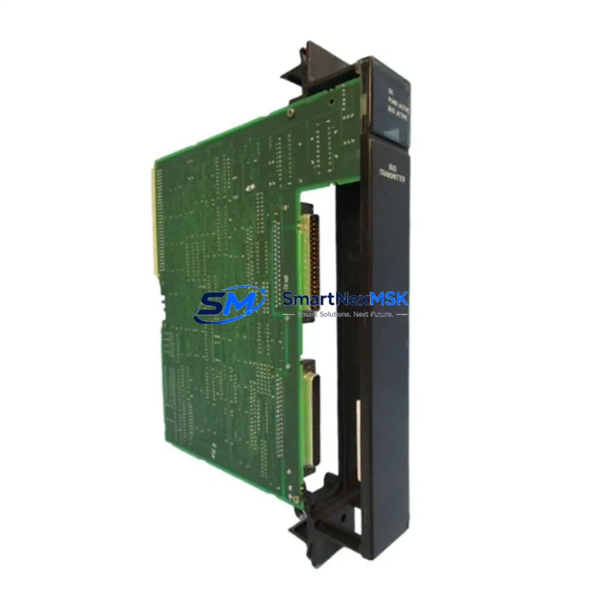
GE IC697BEM713 Maintenance-Ready Spare for Series 90-70 Automation
The GE IC697BEM713 is a Bus Expansion Module (BEM) designed for the GE Series 90-70 PLC platform — one of the most widely deployed large-scale programmable logic controller architectures in heavy industry, power generation, petrochemical processing, and discrete manufacturing. As aging Series 90-70 systems continue to operate well beyond their original design life, maintaining a verified, tested spare of the IC697BEM713 is a critical element of any responsible maintenance strategy.
The IC697BEM713 serves as the rack-to-rack communication interface, enabling the Series 90-70 CPU rack to expand I/O capacity across remote expansion racks via the Series 90-70 I/O bus. Loss of this module results in immediate loss of all I/O in the connected expansion rack — a failure mode that can trigger unplanned shutdowns across entire production lines. For maintenance engineers managing aging control infrastructure, having a pre-tested IC697BEM713 on the shelf is not optional; it is a downtime-prevention imperative.
Each IC697BEM713 unit supplied by SMARTNEXMSK is sourced from verified industrial channels, inspected for physical integrity, and functionally tested prior to shipment. All units carry a 12-month warranty covering manufacturing defects and functional failures under normal operating conditions.
Spare Maintenance Table
| Parameter | Specification |
|---|---|
| Part Number | IC697BEM713 |
| Brand | General Electric (GE Automation) |
| Series | GE Series 90-70 |
| Module Type | Bus Expansion Module (BEM) — Local / Remote |
| Bus Interface | Series 90-70 I/O Bus (parallel backplane bus) |
| Compatible Racks | IC697CHS750, IC697CHS782, IC697CHS790 and compatible Series 90-70 expansion racks |
| Compatible CPUs | IC697CPU731, IC697CPU771, IC697CPU781, IC697CPU782, IC697CPU788, IC697CPU789 |
| Operating Voltage | +5 VDC (supplied via rack backplane) |
| Operating Temperature | 0°C to 60°C (32°F to 140°F) |
| Humidity | 5% to 95% non-condensing |
| Mounting | Single-slot, Series 90-70 rack |
| Origin | USA |
| Warranty | 12 Months — tested before shipment |
| Condition | Original / Surplus New / Refurbished (clearly stated per order) |
Maintenance Planning for Continuous Operation
When a maintenance or procurement engineer identifies the IC697BEM713 as a replacement requirement, the replacement event should be treated as a broader system health checkpoint — not an isolated module swap. The IC697BEM713 sits at the intersection of the CPU rack and the expansion I/O rack, meaning its failure or degradation can mask or be caused by issues in adjacent components.
Before or during an IC697BEM713 replacement, engineers should inspect and verify the following associated components:
Power Supply: The IC697PWR711 or IC697PWR724 rack power supply should be load-tested. A marginal power supply delivering unstable +5 VDC or +24 VDC rails is a common root cause of intermittent BEM communication faults. Replace the power supply if output ripple or voltage sag is detected under load.
Expansion Rack Cabling: The IC697CBL700 or IC697CBL701 bus expansion cables connecting the local BEM to the remote BEM should be inspected for connector wear, shield continuity, and cable routing. Damaged or improperly routed bus cables are a leading cause of IC697BEM713 communication errors and should be replaced as a pair with the BEM.
Remote BEM: The IC697BEM713 operates as a matched pair — one local BEM in the CPU rack and one remote BEM in the expansion rack. If one module is replaced, the condition of the paired remote BEM should be evaluated. Mismatched firmware revisions between local and remote BEM units can cause bus initialization failures.
I/O Modules: After restoring bus communication, all I/O modules in the expansion rack — including IC697MDL340 discrete input modules, IC697MDL341 output modules, and IC697ALG230 analog input modules — should be verified for correct status indication and channel-level diagnostics via the programming software.
CPU Module: If the IC697BEM713 fault was accompanied by CPU fault logs, the CPU module itself — such as the IC697CPU771 or IC697CPU782 — should be inspected for firmware currency and memory battery status. A depleted memory backup battery can corrupt configuration data and cause false BEM faults after power cycling.
Backplane Integrity: The rack backplane connectors should be visually inspected for oxidation, bent pins, or debris. Backplane connector issues are often misdiagnosed as BEM failures and will cause recurring faults even after module replacement.
Communications Modules: If the expansion rack hosts a CMM (Communications Module) such as the IC697CMM711 or IC697CMM742, verify that the communications module resumes normal operation after the BEM replacement and that all network nodes reconnect without manual intervention.
Maintaining a minimum spare inventory of one IC697BEM713 local module and one remote module, along with a set of bus expansion cables, is recommended for any facility operating more than two Series 90-70 expansion racks. For facilities with legacy systems approaching 15–20 years of service, a broader spares kit including a backup CPU, power supply, and representative I/O modules provides the most robust protection against extended unplanned downtime.
Site Replacement Workflow
Step 1 — Pre-Replacement Verification: Before removing the IC697BEM713, document the current rack slot assignment, bus address DIP switch settings, and any LED fault indicators. Photograph the module face and cable connections. Confirm the replacement unit matches the original part number and, where possible, the firmware revision.
Step 2 — Controlled Shutdown: Place the PLC CPU in STOP mode via the programming terminal (Proficy Machine Edition or equivalent). Inhibit all outputs and confirm process safety interlocks are engaged before de-energizing the expansion rack. Do not hot-swap the IC697BEM713 — this module does not support live insertion.
Step 3 — Module Removal and Installation: Disconnect the bus expansion cable from the BEM faceplate connector. Remove the module by releasing the top and bottom ejector levers. Insert the replacement IC697BEM713, ensuring full backplane engagement. Reconnect the bus expansion cable and verify connector locking.
Step 4 — DIP Switch Configuration: Verify that the bus address DIP switches on the replacement module are set identically to the removed module. Incorrect bus addressing will prevent the expansion rack from being recognized by the CPU.
Step 5 — Power-Up and Diagnostics: Re-energize the expansion rack and CPU rack. Monitor the BEM status LEDs — the OK LED should illuminate solid green within 10 seconds of power application. Use the programming software to confirm that all I/O modules in the expansion rack are online and reporting correct status.
Step 6 — Functional Test: Execute a controlled I/O test sequence to verify that all discrete and analog channels in the expansion rack are responding correctly. Log the replacement event in the site maintenance management system (CMMS) with the module serial number, date, and technician ID.
This workflow supports rapid recovery from unplanned BEM failures and can typically be completed within 30–60 minutes by a trained maintenance technician, minimizing production impact.
Spare Parts Support FAQ
Q1: Is the IC697BEM713 still available as a new original part, or only as surplus?
GE has transitioned the Series 90-70 platform to end-of-life status, meaning new factory production of the IC697BEM713 has ceased. SMARTNEXMSK sources IC697BEM713 units from verified surplus channels, including decommissioned systems and authorized distributor overstock. Each unit is individually inspected and tested. The condition (surplus new, refurbished, or tested used) is clearly stated for each order. All units carry a 12-month warranty regardless of condition grade.
Q2: How do I verify compatibility between the IC697BEM713 and my existing Series 90-70 rack configuration?
The IC697BEM713 is compatible with all standard Series 90-70 expansion racks (IC697CHS750, IC697CHS782, IC697CHS790) and all Series 90-70 CPUs. Compatibility is determined by the rack type and bus cable type, not by the CPU firmware version. If you are unsure of your rack model or bus cable type, provide your system configuration details to our technical team at [email protected] and we will confirm compatibility before shipment.
Q3: What testing is performed on IC697BEM713 units before shipment?
Each IC697BEM713 undergoes a multi-point inspection covering physical connector integrity, backplane edge connector condition, DIP switch functionality, and powered operational testing in a Series 90-70 test rack. Units that fail any inspection point are rejected and not offered for sale. A test report is available upon request for critical applications.
Q4: What is the recommended spare inventory strategy for facilities operating multiple Series 90-70 expansion racks?
For facilities with 2–4 expansion racks, a minimum of one matched pair of IC697BEM713 (local + remote) plus one set of bus expansion cables is recommended. For facilities with 5 or more expansion racks, or where the Series 90-70 system controls safety-critical processes, a broader spares kit including a backup CPU module, power supply, and representative I/O modules is advisable. SMARTNEXMSK can assist with spare parts planning and long-term supply agreements to ensure continued availability of critical Series 90-70 components.
—
© 2026 SMARTNEXMSK. All rights reserved.
Original Source: https://smartnexmsk.com
Contact: [email protected] | +86 18259474341