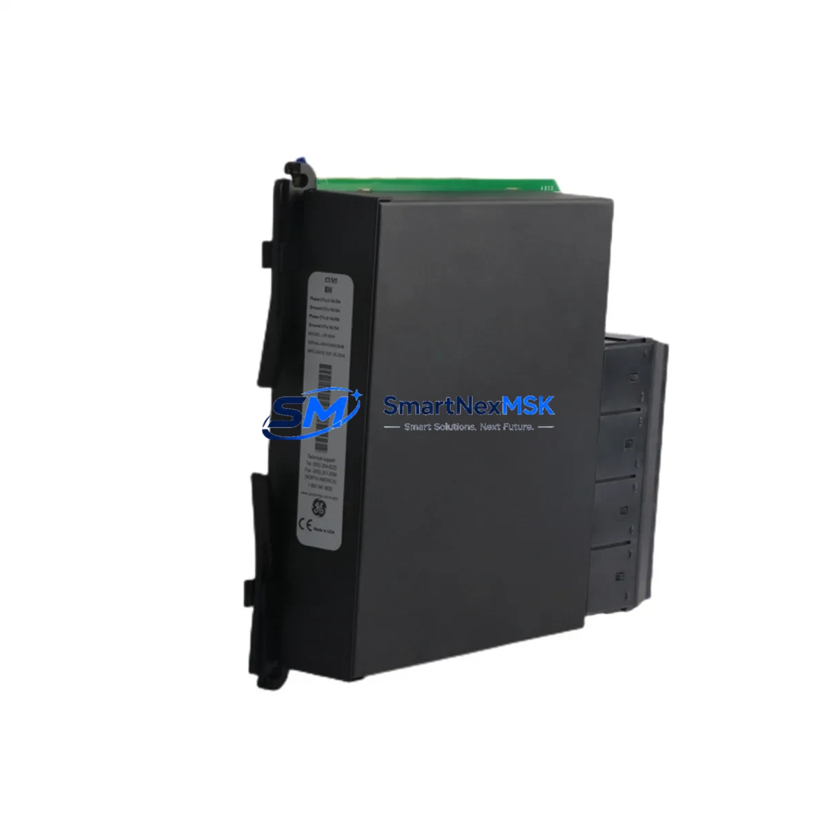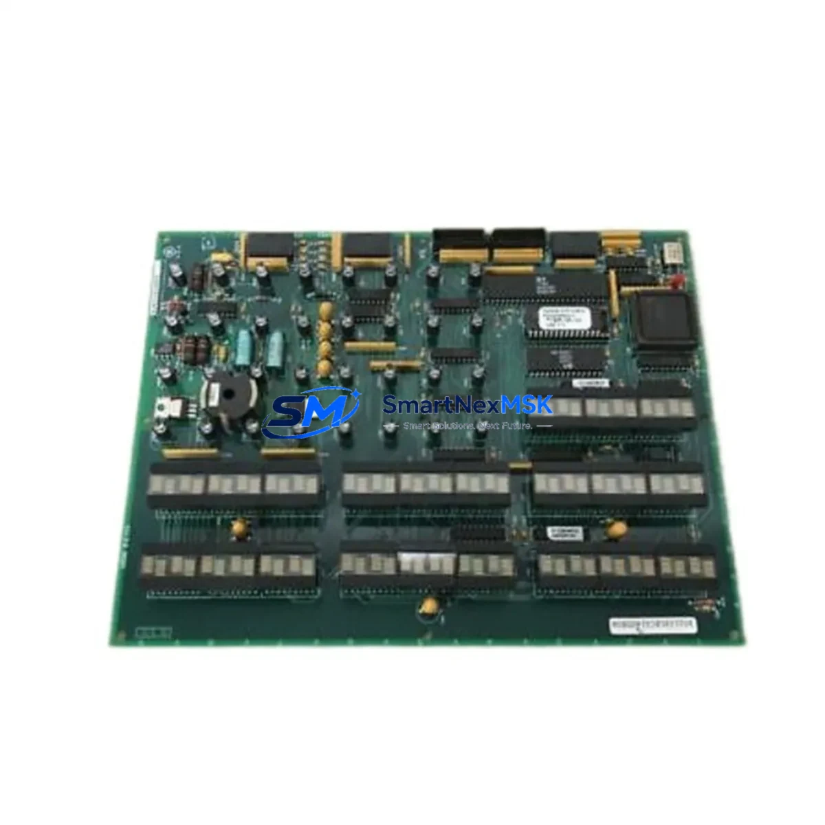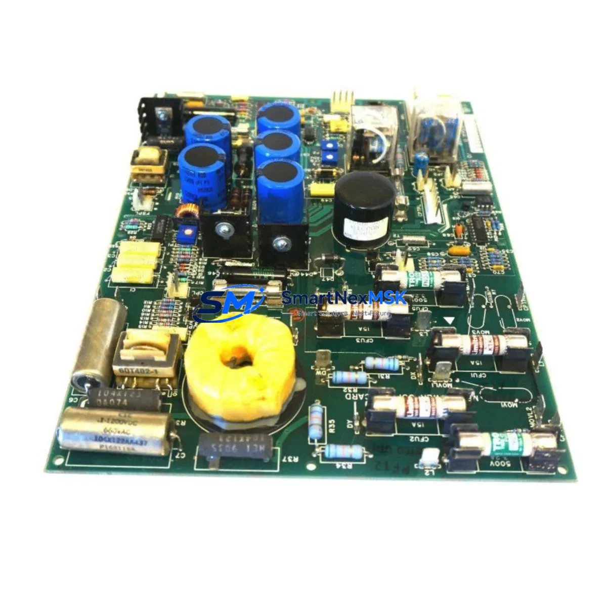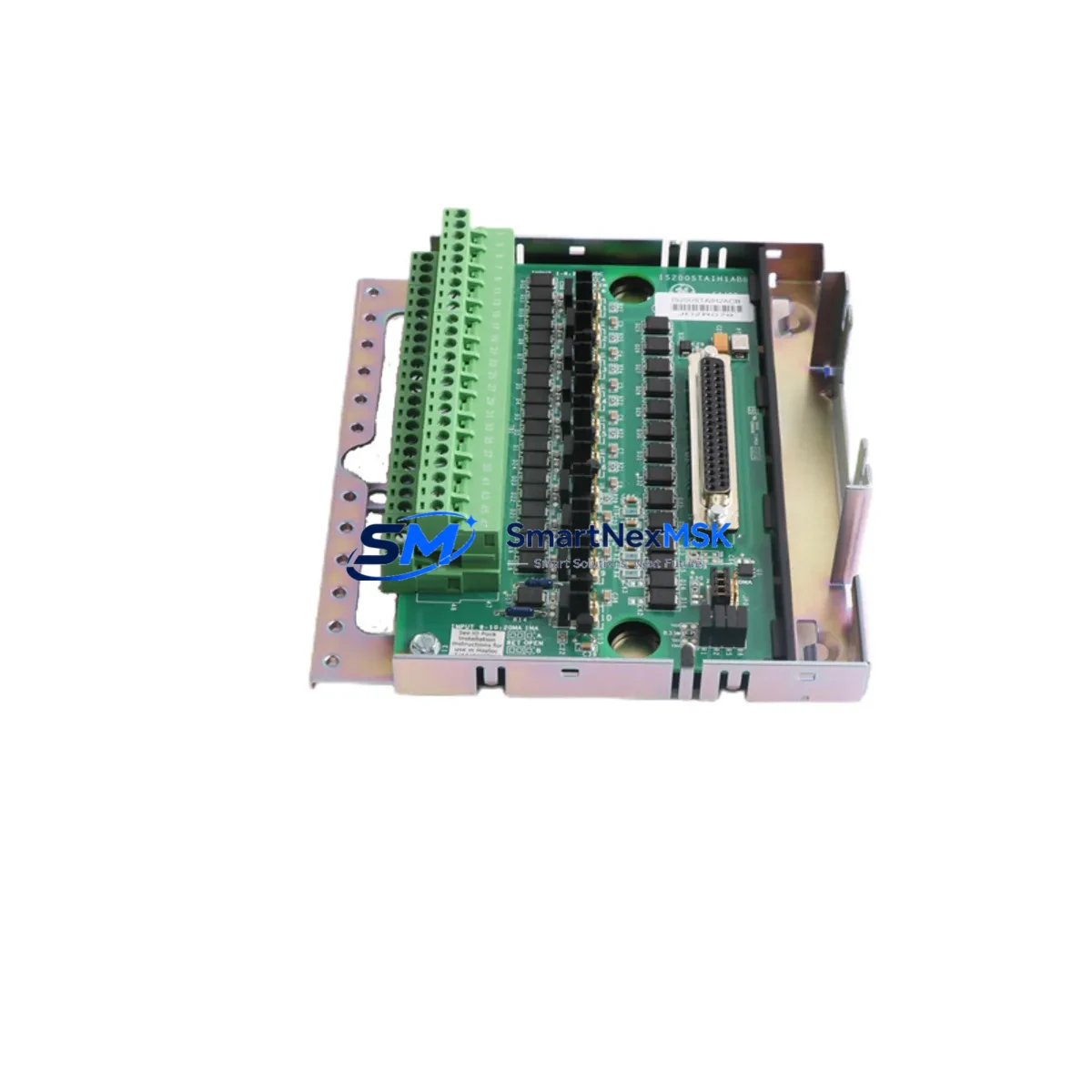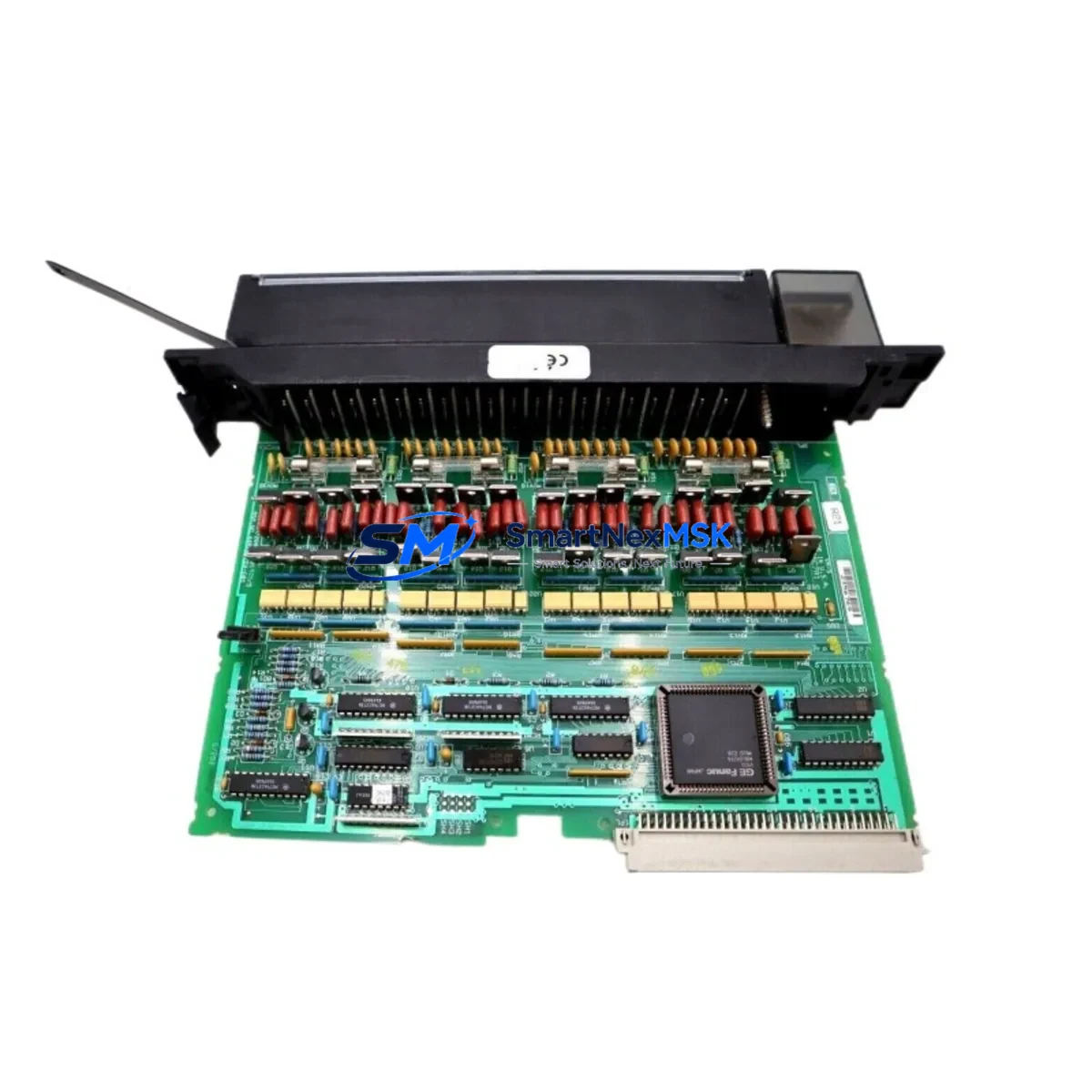
GE IC697MDL350 Retrofit-Ready Discrete Output for Series 90-70 Control Systems
The GE IC697MDL350 is a 32-point, 120VAC discrete output module engineered for the GE Series 90-70 programmable logic controller platform. As legacy Series 90-70 systems approach end-of-life and original spare parts become increasingly scarce, the IC697MDL350 remains one of the most sought-after retrofit and replacement components for industrial facilities operating continuous-process lines, discrete manufacturing cells, and utility control cabinets. This module provides a direct, drop-in upgrade path for aging output infrastructure without requiring rack redesign, program recompilation, or HMI screen remapping — making it the preferred choice for maintenance engineers focused on minimizing planned and unplanned downtime.
Each IC697MDL350 unit shipped by SMARTNEXMSK undergoes pre-shipment functional verification, including output channel actuation testing, backplane communication handshake confirmation, and visual inspection for connector integrity. All units are covered by a 12-month warranty against manufacturing defects and operational failure under normal industrial service conditions.
Upgrade Compatibility Table
| Parameter | IC697MDL350 Specification | Retrofit / Replacement Notes |
|---|---|---|
| Output Type | 32-point discrete, 120VAC | Direct replacement for IC697MDL340 (16-pt) with I/O address remapping required |
| Backplane Interface | Series 90-70 VME-based rack bus | Compatible with IC697CHS750, IC697CHS782, IC697CHS790 rack assemblies |
| Power Consumption | 5VDC from backplane; field side 120VAC | Verify IC697PWR711 or IC697PWR724 power supply capacity before installation |
| Terminal Wiring | 40-pin field wiring connector | Existing field wiring harness typically reusable; verify terminal torque spec |
| Module Address | Slot-based, configured via IC697CPU772 or IC697CPU782 CPU | Confirm I/O map in Logicmaster 90 or Proficy Machine Edition before swap |
| Communication Protocol | Local rack I/O; Genius Bus via IC697BEM711 optional | Remote I/O drops using IC697BEM731 remain unaffected by local module swap |
| HMI Compatibility | Tag-based; no screen changes required for same-slot replacement | iFIX, CIMPLICITY, and third-party SCADA systems unaffected if I/O address unchanged |
| Installation Requirement | Hot-swap not supported; CPU stop required | Schedule during planned maintenance window; backup program before swap |
| Warranty | 12-Month Warranty — covers functional failure under normal operating conditions | |
Retrofit Planning for Existing Automation Systems
Successful integration of the IC697MDL350 into an existing Series 90-70 control system begins well before the module arrives on-site. Engineers should start by auditing the current rack configuration — identifying the chassis model (commonly the IC697CHS750 9-slot or IC697CHS782 12-slot rack), confirming available slot positions, and reviewing the power budget supplied by the installed IC697PWR711 or IC697PWR724 power supply module. The IC697MDL350 draws its logic power from the backplane 5VDC bus, and adding or replacing output modules in a densely populated rack can push the supply toward its rated limit. A margin of at least 10–15% headroom is recommended before committing to the swap.
Terminal wiring is the next critical checkpoint. The IC697MDL350 uses a 40-pin field wiring connector that mates with the module’s front-face terminal block. In most retrofit scenarios, the existing field wiring harness — routed from the control cabinet’s terminal strips to the PLC rack — can be reused without modification, provided the wire gauge, insulation rating, and terminal torque specifications are within tolerance. Engineers should verify that the field-side 120VAC load circuits are de-energized and locked out before disconnecting or reconnecting the wiring connector.
On the software side, the module address is determined by its physical slot position within the rack and must match the I/O configuration stored in the CPU — typically an IC697CPU772 or IC697CPU782 processor. Before removing the legacy module, export a full program backup using Logicmaster 90-70 or Proficy Machine Edition, and document the existing I/O reference table. If the replacement IC697MDL350 occupies the same slot as the failed module, no program changes are required. If the slot position changes — for example, due to rack consolidation or a move to a different chassis — the I/O reference addresses must be updated in the ladder logic and any associated HMI tag databases.
For systems that use Genius Bus communication, the IC697BEM711 Bus Controller or IC697BEM731 Remote I/O Scanner modules handle the distributed I/O drops independently of the local rack output modules. Replacing a local IC697MDL350 does not affect Genius Bus device configurations, but engineers should confirm that the bus controller’s device map is current and that no address conflicts exist after the swap. Similarly, if the system includes an IC697CMM711 or IC697CMM742 communications module for Ethernet or serial connectivity, those links remain active during a local module replacement as long as the CPU is returned to RUN mode promptly after the swap.
For facilities upgrading from older IC697MDL340 (16-point) output modules to the IC697MDL350 (32-point), the expanded I/O capacity allows consolidation of two legacy modules into one slot, freeing rack space for additional IC697MDL671 analog input modules, IC697MDL240 discrete input modules, or future expansion. This consolidation strategy is particularly effective in control cabinets where rack space is constrained and adding a second IC697CHS750 chassis is not practical.
Downtime Control During System Migration
Minimizing production downtime during a Series 90-70 output module replacement requires a structured pre-swap checklist and a clear rollback plan. Begin by placing the IC697CPU772 or IC697CPU782 CPU into STOP mode and confirming that all 32 output channels on the IC697MDL350 being replaced are de-energized — verify at the field device level, not just at the module status LEDs. Engage lockout/tagout procedures on the 120VAC field power circuits before touching the wiring connector.
With the program backup confirmed and the I/O address map documented, the physical swap of the IC697MDL350 typically takes under five minutes. After seating the replacement module and reconnecting the field wiring connector, return the CPU to RUN mode and observe the module’s status LED — a solid green RUN indicator confirms successful backplane communication and output channel initialization. Scan the first 10–15 rungs of the ladder program that reference the affected output references to confirm expected coil states before releasing the process to automatic control.
For critical continuous-process applications where even a brief CPU STOP is unacceptable, consider a parallel rack strategy: install a second IC697CHS750 rack with a pre-configured IC697MDL350 and transfer output wiring in stages during a scheduled low-production window. This approach, combined with the IC697BEM731 remote I/O capability, allows output capacity to be migrated incrementally without a full system shutdown. Document each stage of the migration in the plant’s change management system and retain the pre-swap program backup for a minimum of 90 days post-commissioning.
Retrofit Support FAQ
Q1: Is the IC697MDL350 a direct drop-in replacement for the IC697MDL340?
The IC697MDL350 (32-point) and IC697MDL340 (16-point) share the same Series 90-70 backplane interface and physical form factor, but the point count differs. A direct slot-for-slot swap requires updating the I/O reference map in the CPU configuration to account for the additional 16 output points. If only 16 points are needed, the extra channels can be left unassigned in the program without affecting system operation.
Q2: What commissioning steps are required after installing the IC697MDL350?
After physical installation, place the CPU in RUN mode and verify the module’s RUN LED status. Use Logicmaster 90-70 or Proficy Machine Edition to perform an online I/O force test on each output channel, confirming field device response. Check the CPU fault table for any I/O configuration mismatch faults. For systems with CIMPLICITY or iFIX SCADA, confirm that output tag values are updating correctly before releasing to automatic control.
Q3: Can the IC697MDL350 be used in a rack with mixed voltage output modules?
Yes. The Series 90-70 rack architecture supports mixed module types within the same chassis. The IC697MDL350 (120VAC) can coexist in the same IC697CHS750 or IC697CHS782 rack with DC output modules such as the IC697MDL753 (24VDC) or relay output modules such as the IC697MDL940, provided the total backplane power budget is not exceeded.
Q4: What does the 12-month warranty cover, and how is a warranty claim initiated?
The 12-month warranty covers functional failure of the IC697MDL350 under normal industrial operating conditions, including backplane communication faults, output channel failure, and component defects. It does not cover damage resulting from incorrect installation, overvoltage, or physical impact. To initiate a warranty claim, contact SMARTNEXMSK at [email protected] with the order number, module serial number, and a description of the fault. Replacement or repair is typically processed within 5–7 business days of fault confirmation.
© 2026 SMARTNEXMSK. All rights reserved.
Original Source: https://smartnexmsk.com
Contact: [email protected] | +86 18259474341