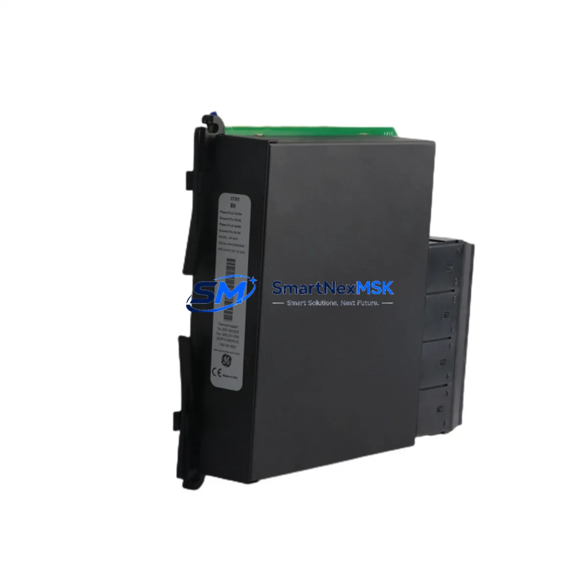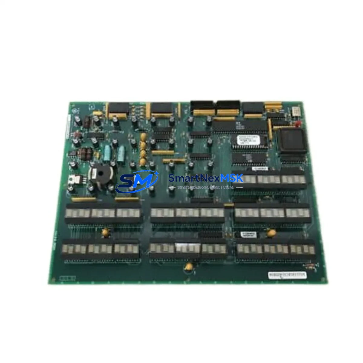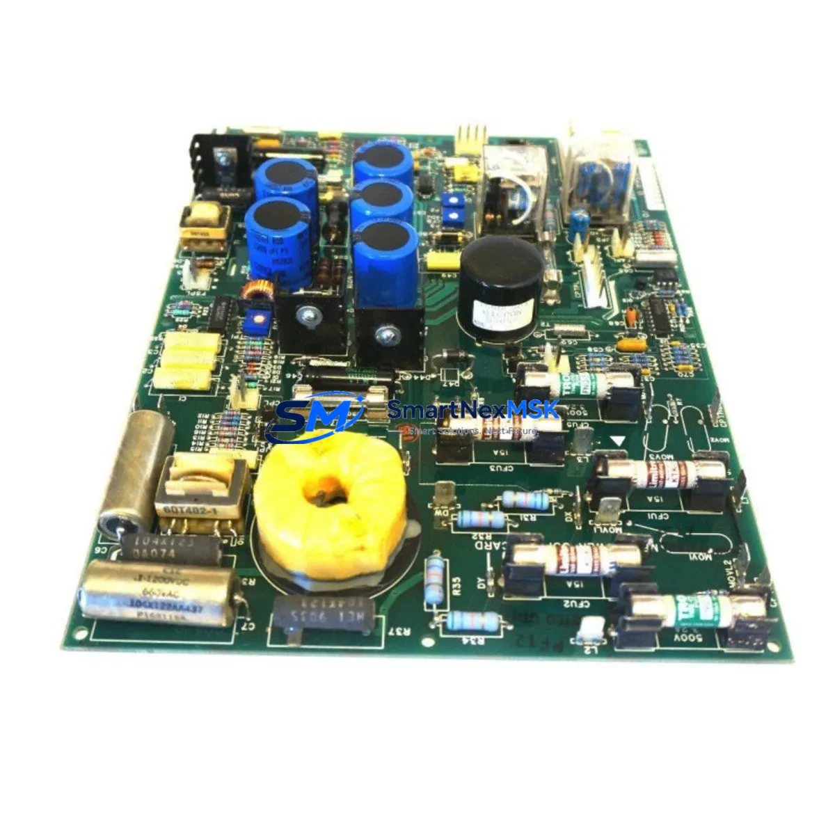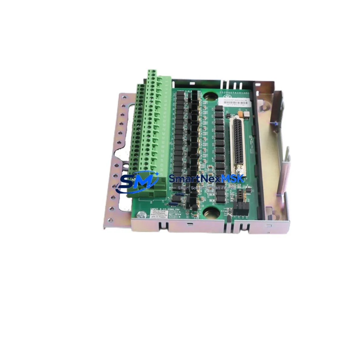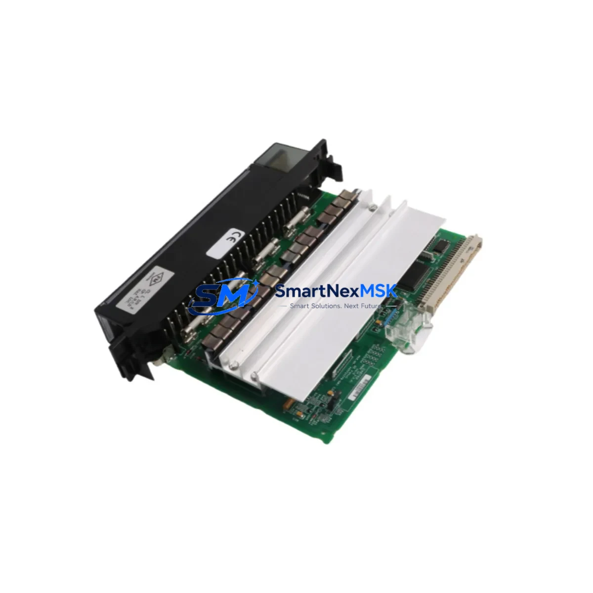
GE IC697MDL740 Retrofit-Ready Discrete Output Module for Series 90-70 Control Systems
The GE IC697MDL740 is a 120VAC discrete output module engineered for the GE Fanuc Series 90-70 programmable logic controller platform. With 16 isolated output channels rated at 120VAC/2A per point, this module is the direct retrofit solution for aging or discontinued output modules in legacy Series 90-70 control cabinets. Whether you are replacing a failed IC697MDL741, upgrading from an earlier-generation IC697MDL700, or modernizing a multi-rack system that has been in continuous service for over a decade, the IC697MDL740 provides a verified drop-in replacement path with no rack modification, no backplane rewiring, and no CPU firmware upgrade required.
Industrial facilities running Series 90-70 architectures — including those built around the IC697CPU772 or IC697CPU781 central processing units — frequently encounter output module failures caused by triac aging, surge damage, or simple end-of-service-life wear. Sourcing a verified replacement with full compatibility documentation is critical to minimizing unplanned downtime. The IC697MDL740 ships pre-tested, with each unit validated against GE Fanuc output specifications before dispatch, and is backed by a 12-month warranty.
Upgrade Compatibility Table
| Parameter | IC697MDL740 (This Unit) | Notes / Retrofit Guidance |
|---|---|---|
| Output Type | 120VAC Discrete, Triac | Direct replacement for IC697MDL741 and IC697MDL700 |
| Output Points | 16 Points | Identical channel count; no I/O address remapping required |
| Output Current | 2A per point, 8A per group | Verify field device load does not exceed group rating |
| Backplane Interface | Series 90-70 VME Backplane | Compatible with IC697CHS750, IC697CHS782, IC697CHS790 racks |
| Module Slot | Any I/O slot in Series 90-70 rack | Slot address must match original module address in CPU configuration |
| Communication | Local rack I/O bus | No separate communication module required for local rack installation |
| Remote I/O Compatibility | Via IC697BEM731 or IC697BEM733 | Confirm bus controller firmware revision supports module type |
| Programming Software | Proficy Machine Edition / Logicmaster 90 | No hardware configuration change needed if slot address is preserved |
| Installation | Hot-swap not supported; power-down required | Follow GE Fanuc GFK-0356 installation procedure |
| Warranty | 12 Months | Covers manufacturing defects; includes pre-shipment functional test report |
Retrofit Planning for Existing Automation Systems
A successful IC697MDL740 retrofit begins well before the module arrives on site. Engineers responsible for the upgrade should first audit the existing rack configuration, documenting the slot position of the failed or aging output module, the I/O reference addresses assigned in the CPU hardware configuration, and the field wiring terminal assignments on the module’s terminal block. The IC697MDL740 uses the same 40-pin connector and terminal block layout as its predecessors, so field wiring can typically be transferred directly without re-labeling or re-routing.
Power budget verification is the next critical step. The Series 90-70 rack power supply — commonly the IC697PWR710 or IC697PWR711 — must have sufficient 5VDC backplane capacity and 120VAC field power capacity to support the replacement module under full load. If the existing power supply is already operating near its rated output, consider upgrading to the higher-capacity IC697PWR724 as part of the same retrofit window.
For systems using remote I/O drops connected via the IC697BEM731 Bus Transmitter Module or the IC697BEM733 Bus Receiver Module, confirm that the remote drop rack housing the IC697MDL740 is correctly addressed and that the bus controller’s I/O map reflects the module’s output reference range. Mismatched I/O maps are a common source of post-retrofit faults that can be avoided with a pre-installation configuration review in Proficy Machine Edition.
In multi-rack systems where the Series 90-70 CPU communicates with operator interface panels — such as legacy QuickPanel HMI terminals or third-party SCADA systems connected via the IC697CMM711 Ethernet Interface Module — verify that output tag addresses referenced in HMI screens and SCADA graphics match the I/O reference addresses of the replacement module. A mismatch here will not cause a CPU fault but will result in incorrect HMI display states, which can mislead operators during the commissioning phase.
If the control system includes analog I/O modules such as the IC697ALG320 Analog Input Module or the IC697ALG390 Analog Output Module in adjacent slots, ensure that the rack’s backplane integrity is verified before and after module swap. Backplane connector pins on older racks can develop intermittent contact issues that only manifest under vibration or thermal cycling, and a retrofit window is the ideal time to inspect and clean the VME backplane connectors.
For systems where the original output module was configured with a specific fault state (hold-last-state or default-off), confirm that the replacement IC697MDL740 is configured identically in the CPU hardware configuration file. This setting is stored in the CPU, not the module, but verifying it during commissioning prevents unexpected field device behavior on the first power-up after the swap.
Downtime Control During System Migration
Minimizing production downtime during an IC697MDL740 swap requires a structured pre-outage preparation protocol. Before taking the system offline, export the current hardware configuration from Proficy Machine Edition or Logicmaster 90 and save a verified backup of the CPU program, including all data blocks, I/O configuration tables, and communication parameters. Store this backup on an offline programming device — such as a laptop with the IC690ACC901 programming cable — so that the original program can be reloaded immediately if the replacement module triggers an unexpected configuration mismatch fault.
During the physical swap, de-energize the rack power supply and verify zero voltage at the module’s field terminals before disconnecting the terminal block. Transfer the terminal block to the replacement IC697MDL740, confirm that all field wiring connections are secure, and re-seat the module firmly into the rack slot. On power-up, the CPU will perform an automatic I/O configuration check. If the slot address and module type match the stored hardware configuration, the CPU will transition to RUN mode without requiring a hardware configuration download, preserving the existing program logic and all retentive data values.
For facilities that cannot tolerate even a brief loss of output control, consider pre-staging a spare rack with the IC697MDL740 already installed and configured, allowing a rack-level swap rather than a module-level swap. This approach, combined with pre-tested spare IC697CHS750 racks and pre-loaded CPU program backups, can reduce total system downtime to under 15 minutes for a single-rack output module replacement.
After the swap, conduct a point-by-point output verification test by forcing each of the 16 output channels from the programming terminal and confirming correct field device response. Document the test results and retain them as part of the site’s maintenance record. All IC697MDL740 units supplied by SMARTNEXMSK include a pre-shipment functional test report confirming that each output channel was verified at rated voltage and current before dispatch.
Retrofit Support FAQ
Q1: Is the IC697MDL740 a direct drop-in replacement for the IC697MDL741?
Yes. The IC697MDL740 and IC697MDL741 share the same backplane connector, slot form factor, I/O reference addressing scheme, and field terminal block layout. No hardware configuration change is required in the CPU if the replacement module is installed in the same rack slot as the original. Verify the output voltage rating (120VAC) matches your field device requirements before installation.
Q2: Do I need to download a new hardware configuration to the CPU after installing the IC697MDL740?
Not if the replacement module is the same type and is installed in the same slot. The Series 90-70 CPU stores the hardware configuration internally and will automatically recognize the IC697MDL740 as a valid module in that slot. A configuration download is only required if the slot address has changed or if the original configuration file was lost.
Q3: What field wiring and terminal block considerations apply during the swap?
The IC697MDL740 uses the same 40-pin removable terminal block as earlier Series 90-70 discrete output modules. Field wiring can be transferred directly by removing the terminal block from the failed module and inserting it into the replacement unit. Before re-energizing, verify that all terminal screws are torqued to specification and that no wires were disturbed during the transfer. Confirm that the 120VAC field power source is correctly fused for the module’s group current rating.
Q4: What does the 12-month warranty cover, and what testing is performed before shipment?
Every IC697MDL740 unit supplied by SMARTNEXMSK undergoes a pre-shipment functional test in which all 16 output channels are verified at rated voltage and current. The 12-month warranty covers manufacturing defects and functional failures under normal operating conditions. A test report is included with each shipment. For warranty claims, contact [email protected] with the unit serial number and a description of the observed fault.
© 2026 SMARTNEXMSK. All rights reserved.
Original Source: https://smartnexmsk.com
Contact: [email protected] | +86 18259474341