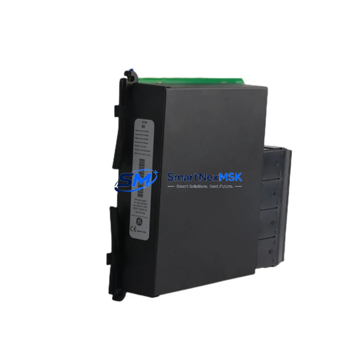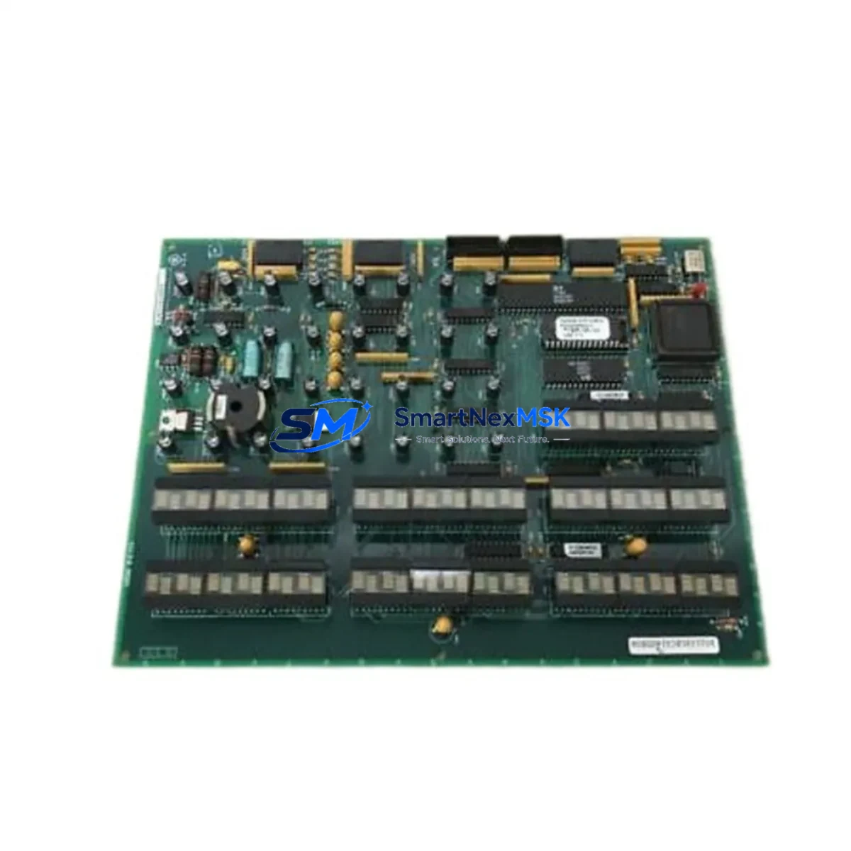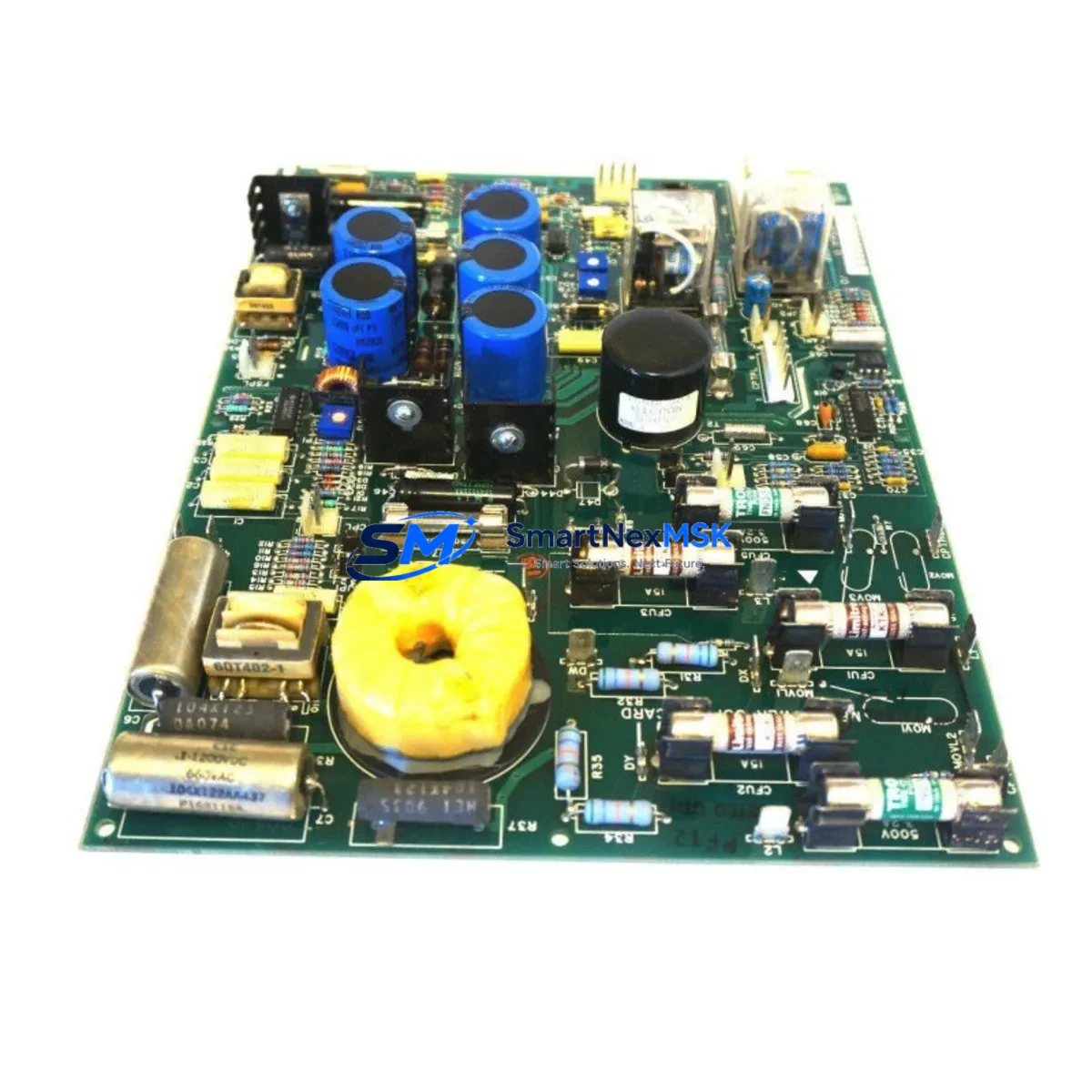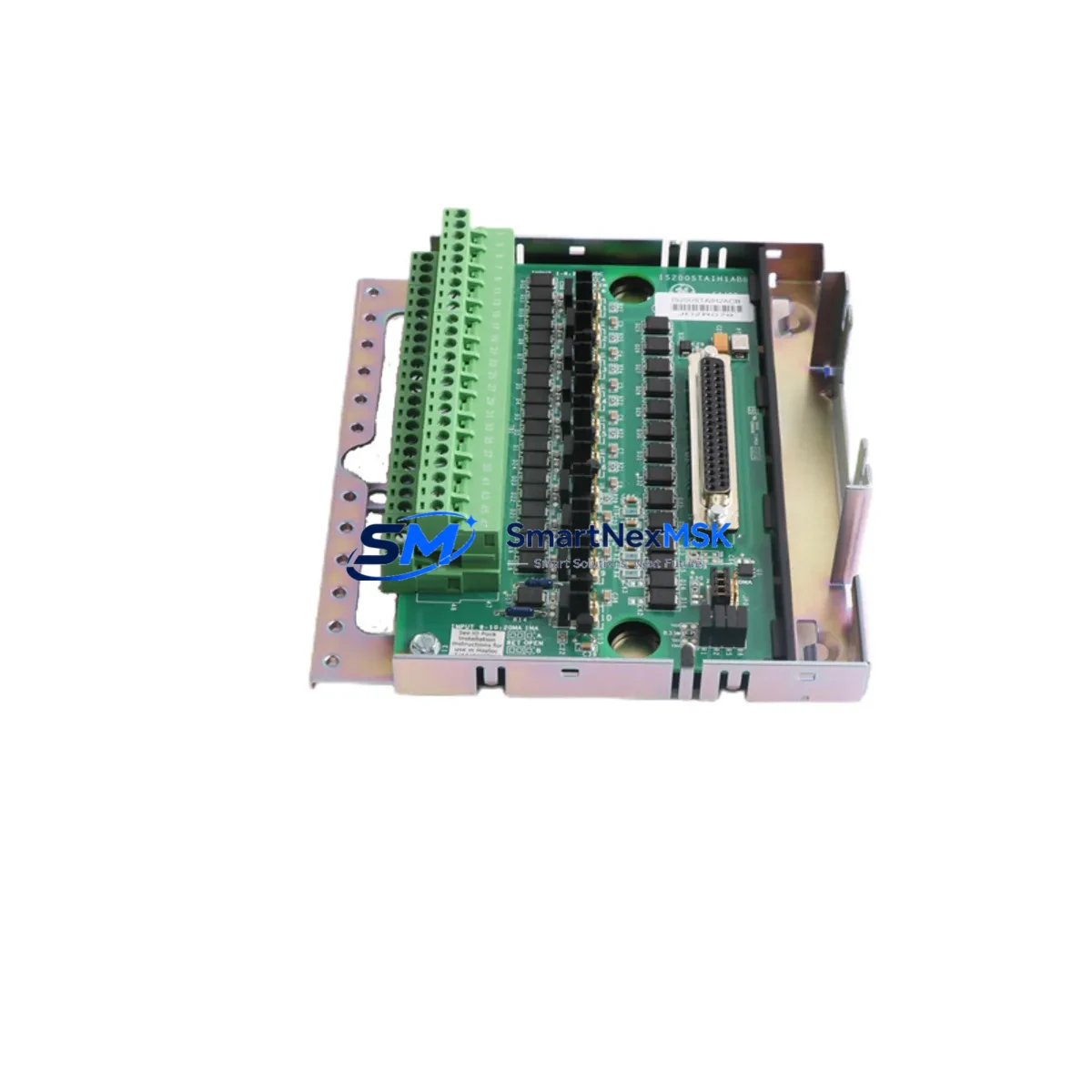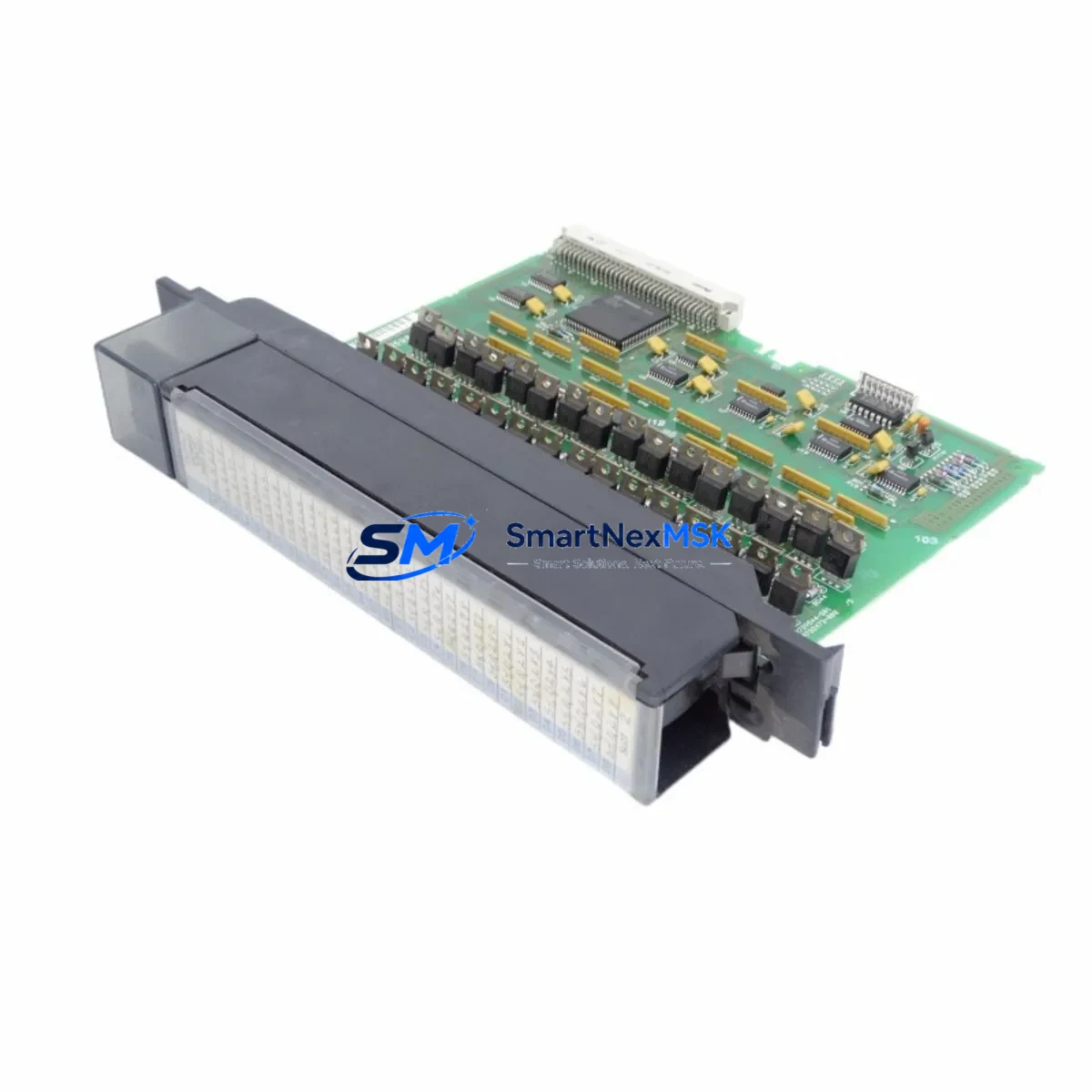
GE IC697MDL750 Retrofit-Ready Digital Output for Series 90-70 Control Systems
The GE IC697MDL750 is a 32-point, 24/48Vdc digital output module engineered for the GE Series 90-70 programmable logic controller platform. As legacy Series 90-70 systems approach end-of-support and original spare parts become increasingly scarce, the IC697MDL750 remains one of the most sought-after retrofit components for engineers tasked with extending the operational life of existing control cabinets, upgrading aging I/O infrastructure, or executing a controlled migration to a modern automation architecture. Whether you are replacing a failed output module on a running production line or planning a phased system modernization, this module provides a verified, drop-in compatible solution that minimizes engineering risk and reduces unplanned downtime.
Upgrade Compatibility Table
| Parameter | IC697MDL750 Specification | Retrofit Notes |
|---|---|---|
| Output Points | 32 points, sourcing | Verify field wiring terminal block pitch matches existing cabinet layout |
| Output Voltage | 24/48Vdc | Confirm field power supply capacity before installation; replace IC697PWR711 or IC697PWR724 if undersized |
| Backplane Interface | Series 90-70 VME-based backplane | Compatible with IC697CHS750, IC697CHS782, and IC697CHS790 rack assemblies |
| Module Address | Rack/slot configurable via Logicmaster 90 or Proficy Machine Edition | Re-use existing rack/slot address from replaced module; no program re-addressing required if slot position is preserved |
| Communication Compatibility | Local I/O bus; compatible with IC697CMM711 and IC697CMM742 communication modules | No protocol migration required for local I/O replacement |
| Installation | Standard Series 90-70 module form factor | No mechanical modification to rack or cabinet required |
| Replacement Recommendation | Direct drop-in for failed or end-of-life IC697MDL750 units | Confirm firmware revision compatibility with CPU module (IC697CPU731, IC697CPU771, IC697CPU782) |
| Commissioning Focus | Force output test, I/O scan verification, field device response check | Use Logicmaster 90 or Proficy ME online monitoring during first power-on |
| Warranty | 12 months from shipment date | Covers manufacturing defects; includes pre-shipment functional test report |
Retrofit Planning for Existing Automation Systems
Successful integration of the IC697MDL750 into an existing Series 90-70 control system requires a structured pre-installation review. Begin by auditing the current rack assembly — whether an IC697CHS750 five-slot chassis or an IC697CHS790 ten-slot chassis — to confirm available slot positions and backplane bus integrity. Inspect the power supply module, typically an IC697PWR711 (24Vdc input) or IC697PWR724 (120/240Vac input), to verify that total rack power budget accommodates the additional output load current introduced by the replacement module. Undersized power supplies are a common root cause of intermittent faults following module swaps and must be addressed before commissioning.
Next, review the terminal block wiring on the existing I/O module. The IC697MDL750 uses a 40-pin field wiring connector; confirm that the existing field cable assembly matches the pinout and that wire ferrules or ring terminals are in serviceable condition. If the original wiring documentation is unavailable, perform a point-by-point continuity check against the field device list before energizing the replacement module.
For systems running Logicmaster 90 software on a legacy programming terminal, or those that have been migrated to Proficy Machine Edition on a modern workstation connected via an IC690USB901 programming cable or IC693CBL316 serial cable, the hardware configuration file must be opened and the replacement module confirmed in the correct rack and slot position. If the CPU module — such as an IC697CPU771 or IC697CPU782 — was previously configured with the failed module’s I/O map, no changes to the ladder logic program are required provided the slot address is preserved. However, if the module is being relocated to a different slot due to rack reconfiguration, all affected output references (%Q addresses) must be remapped and the program re-downloaded.
In systems where the Series 90-70 rack communicates upstream via a GE Genius Bus Controller (IC697BEM711) or interfaces with a CIMPLICITY HMI station, verify that the I/O point tags referenced in the HMI graphic screens correspond to the correct %Q addresses after any slot reassignment. Failure to synchronize HMI tag databases with updated hardware configurations is a frequent source of post-retrofit alarm nuisance and operator confusion. Coordinate with the HMI engineering team to perform a full tag audit before returning the system to production.
Where the control system includes remote I/O drops connected via IC697BEM731 Bus Expansion Modules or communicates with variable frequency drives, servo controllers, or third-party field devices over Modbus RTU through an IC697CMM711 communications module, confirm that the output module replacement does not affect the polling cycle or scan time of the CPU. A brief online monitoring session using Proficy Machine Edition’s data watch table will confirm stable I/O scan performance before the system is handed back to operations.
Downtime Control During System Migration
Minimizing production downtime during an IC697MDL750 replacement requires advance preparation and a disciplined hot-swap or cold-swap protocol. For planned maintenance windows, the recommended approach is to pre-stage the replacement module, verify its pre-shipment test documentation, and prepare a module swap checklist that includes power-down sequence, ESD precautions, module extraction, insertion, power-up, and I/O force test steps. The entire physical swap can typically be completed in under 15 minutes by a trained technician familiar with the Series 90-70 platform.
Before initiating the swap, use the CPU’s online monitoring capability to capture a snapshot of the current output status table. This snapshot serves as a reference for verifying that all outputs return to their correct states after the replacement module is commissioned. If the process requires outputs to be held in a safe state during the swap — for example, to prevent actuator movement or valve closure — use the CPU’s I/O override or force function to lock critical outputs before removing the failed module.
For systems where a cold swap is not feasible due to continuous process requirements, consult the system integrator or OEM regarding the feasibility of a redundant I/O architecture using a secondary IC697MDL750 in a hot-standby rack configuration. While the standard Series 90-70 architecture does not natively support hot-swap I/O, some installations have implemented manual transfer switching at the field terminal level to achieve near-zero-downtime module replacement. Document the transfer procedure and train operations personnel before executing in a live environment.
After the replacement module is installed and powered, perform a structured commissioning sequence: confirm module status LED indication, execute a forced output test on all 32 points, verify field device response, and clear all CPU fault logs. Record the commissioning results and retain the pre-shipment test report supplied with the IC697MDL750 as part of the maintenance record for the control system.
Retrofit Support FAQ
Q1: Is the IC697MDL750 a direct replacement for a failed unit in the same rack slot?
Yes. The IC697MDL750 is a direct drop-in replacement for any existing IC697MDL750 installed in a Series 90-70 rack. No hardware configuration changes are required in Logicmaster 90 or Proficy Machine Edition provided the module occupies the same rack and slot position. The CPU will recognize the replacement module automatically on the next power cycle or online configuration update.
Q2: What commissioning steps are required after installation?
After physical installation, power up the rack and confirm the module’s RUN LED is active and no fault LEDs are illuminated. Use Logicmaster 90 or Proficy Machine Edition to go online with the CPU and verify that the module appears correctly in the hardware configuration. Perform a forced output test on all 32 points to confirm field wiring continuity and field device response. Clear any CPU I/O fault logs and document the commissioning results before returning the system to automatic operation.
Q3: How do I verify wiring compatibility before installation?
Compare the field wiring connector pinout of the replacement IC697MDL750 against the existing terminal block wiring documentation. The module uses a standard 40-pin Series 90-70 field connector. If original wiring drawings are unavailable, perform a point-by-point continuity test from the terminal block to each field device before energizing. Confirm that field power supply voltage (24Vdc or 48Vdc) matches the module’s rated input range and that the total output load current does not exceed the module’s rated capacity.
Q4: What does the 12-month warranty cover, and is a test report included?
Every IC697MDL750 shipped by SMARTNEXMSK includes a pre-shipment functional test report confirming that the module has been tested against GE’s original performance specifications. The 12-month warranty covers manufacturing defects and functional failures under normal operating conditions from the date of shipment. Warranty claims are supported by our technical team; contact [email protected] with your order reference and fault description to initiate a warranty assessment.
© 2026 SMARTNEXMSK. All rights reserved.
Original Source: https://smartnexmsk.com
Contact: [email protected] | +86 18259474341