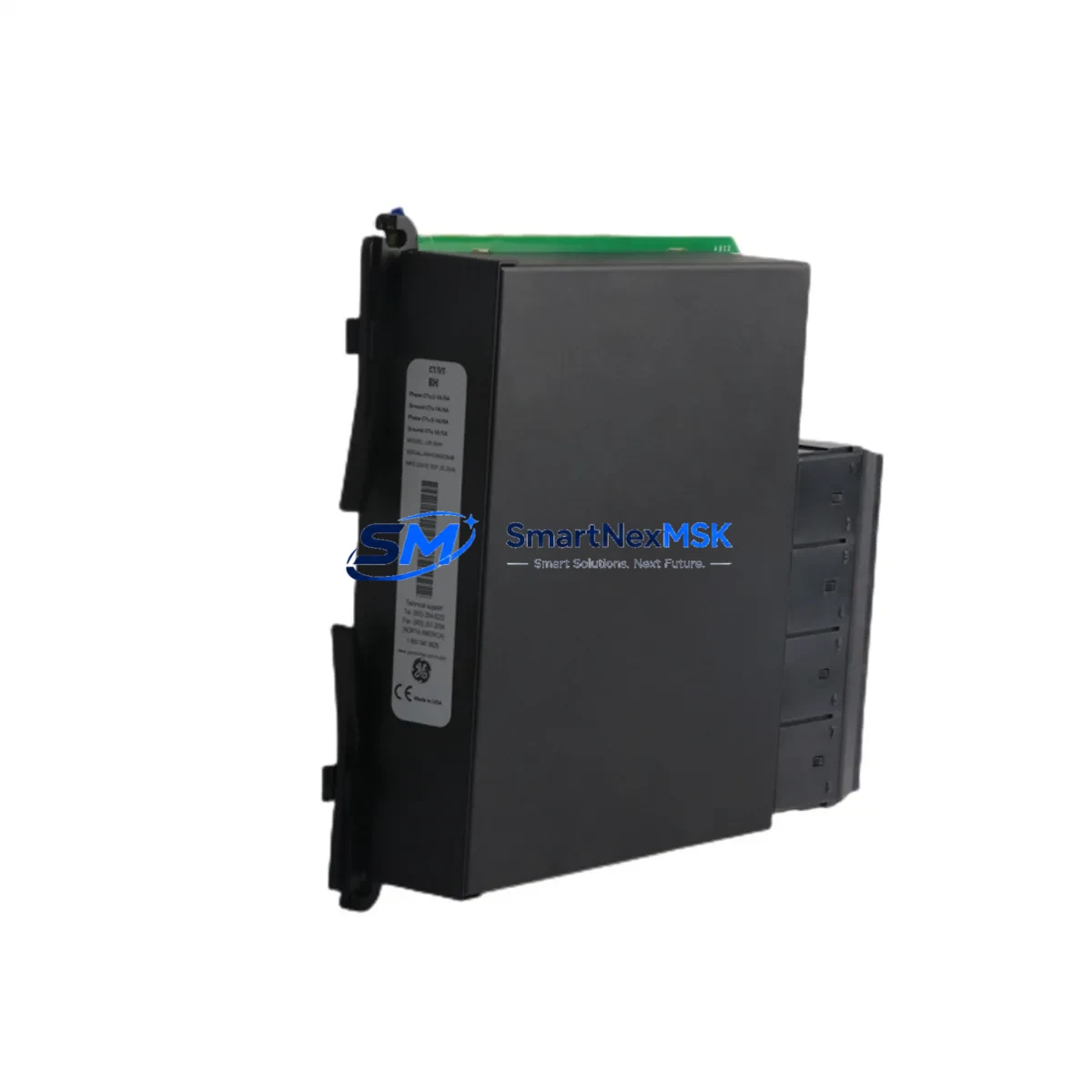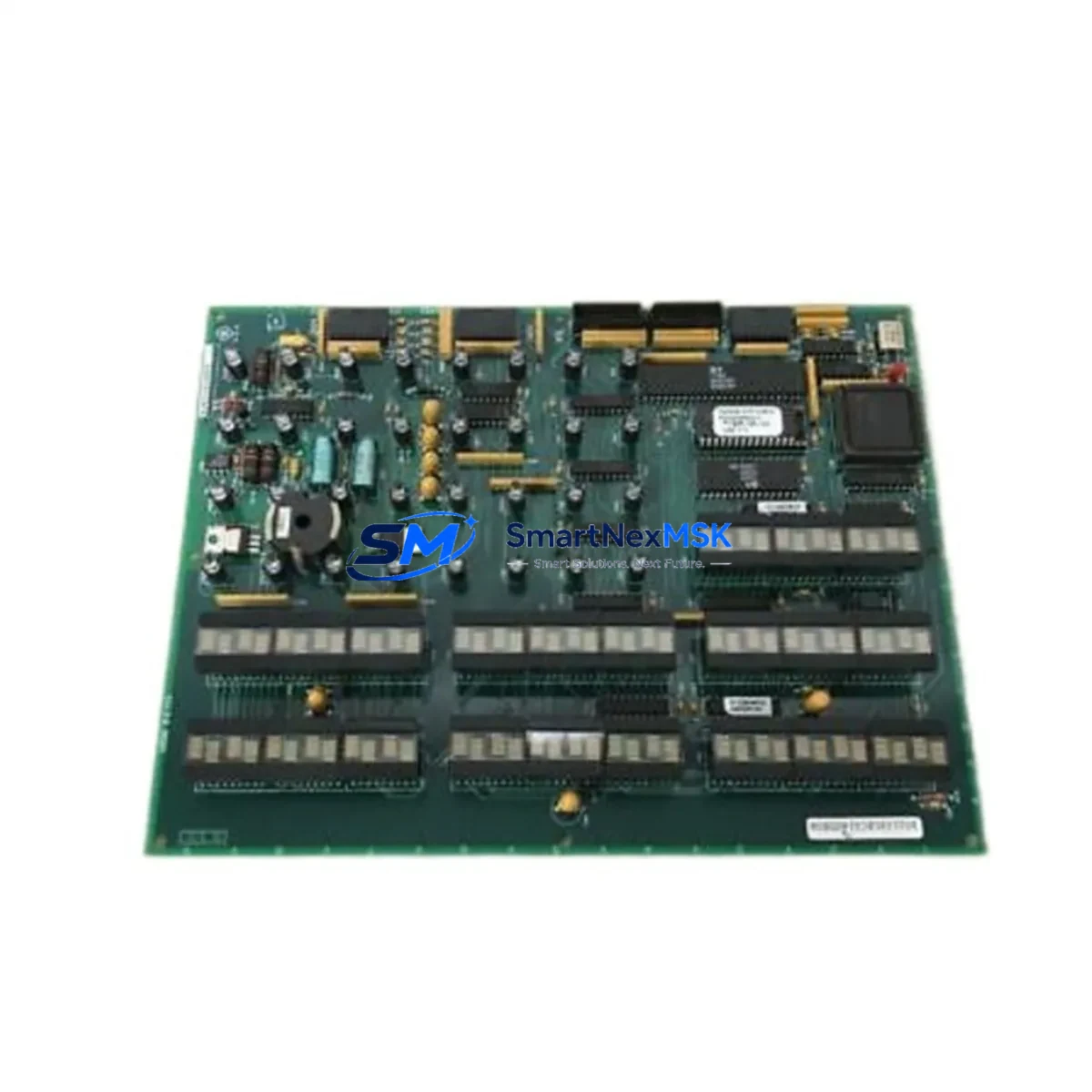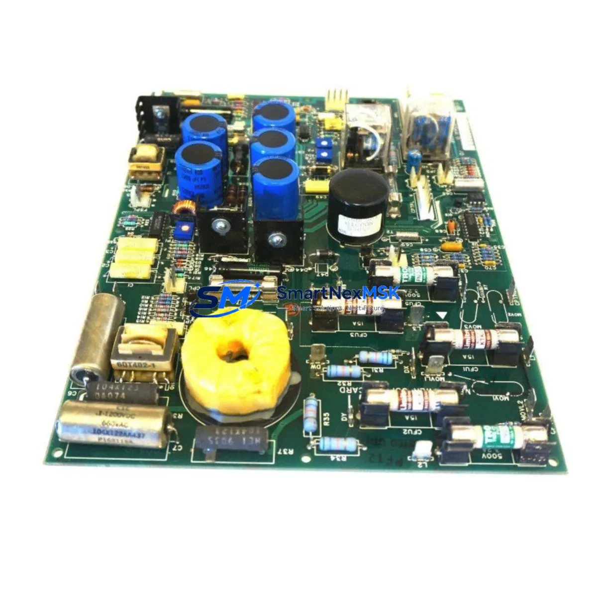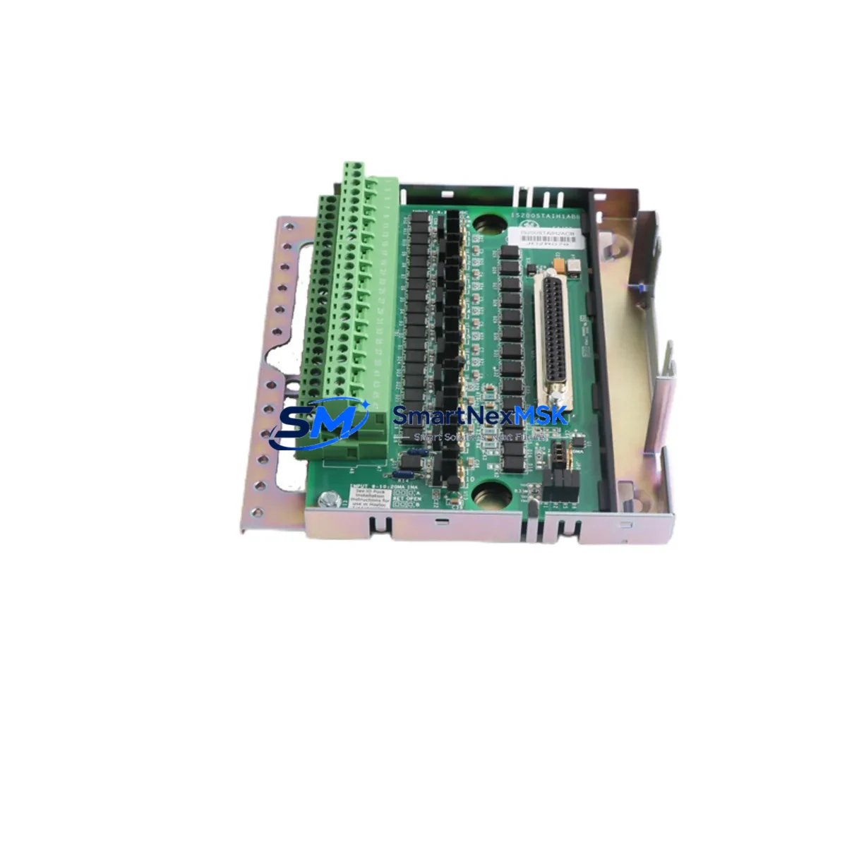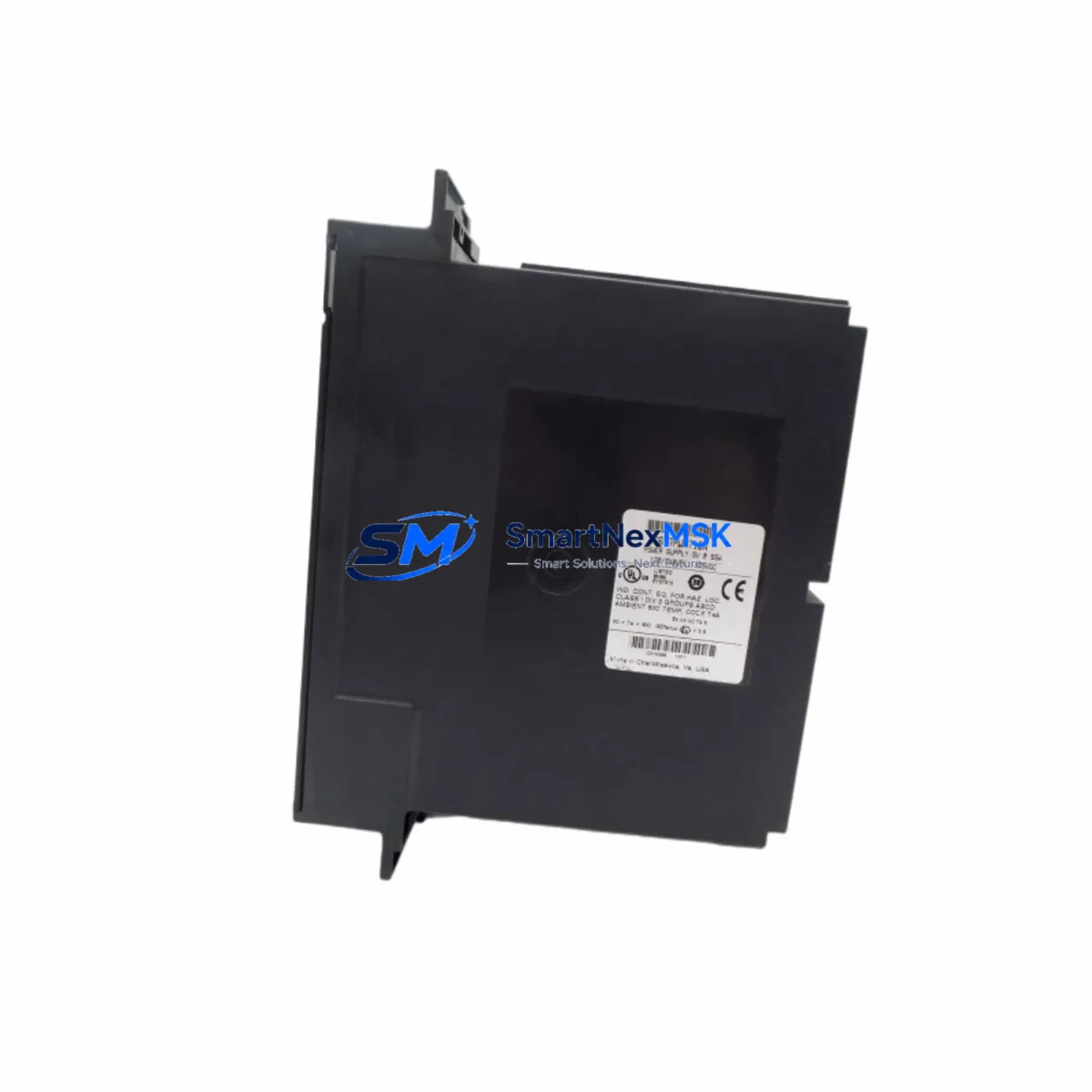
GE IC697PWR710N Maintenance-Ready Spare for Series 90-70 Automation
The GE IC697PWR710N is an original AC input power supply module engineered for GE Series 90-70 PLC rack systems — one of the most extensively deployed programmable logic controller platforms across heavy industry, utilities, water treatment, and process automation. For maintenance engineers responsible for aging control infrastructure, securing a verified spare of the IC697PWR710N is a non-negotiable element of any downtime-prevention strategy. This module delivers regulated DC bus power to the Series 90-70 backplane, sustaining CPU modules, discrete and analog I/O modules, and communication modules installed across the rack. A failed or degraded power supply remains one of the most frequent root causes of unplanned PLC shutdowns, placing the IC697PWR710N at the top of every Series 90-70 critical spare parts list.
Every IC697PWR710N unit supplied by SMARTNEXMSK is sourced from verified industrial channels, subjected to full electrical function testing prior to shipment, and backed by a 12-month warranty from the date of dispatch. Fast order processing, same-day or next-business-day shipping on in-stock units, and long-term supply continuity make this module the preferred choice for both emergency replacement and planned inventory replenishment programs.
Spare Maintenance Table
| Parameter | Specification / Detail |
|---|---|
| Part Number | IC697PWR710N |
| Brand | General Electric (GE) |
| Series Compatibility | GE Series 90-70 PLC Rack Systems |
| Module Type | AC Input Power Supply Module |
| Input Voltage | 120 / 240 VAC, 47–63 Hz (auto-ranging) |
| Output | Regulated DC bus power for Series 90-70 backplane |
| Rack Slot Occupancy | 1 slot — compatible with IC697CHS750, IC697CHS782, IC697CHS790 |
| Compatible CPUs | IC697CPU731, IC697CPU771, IC697CPU772, IC697CPU781, IC697CPU782 |
| Operating Temperature | 0 °C to 60 °C (32 °F to 140 °F) |
| Mounting | Direct rack-mount; tool-free module swap |
| Application Environment | Industrial control cabinets, process automation panels, utility SCADA racks |
| Maintenance Recommendation | Inspect backplane connectors and upstream fusing at each replacement; stock minimum 1 unit per rack type |
| Condition | Original / New-surplus / Refurbished-tested (confirmed at order) |
| Pre-shipment Test | Full electrical function test performed before dispatch |
| Warranty | 12 Months from date of shipment |
| Lead Time | In-stock: same-day or next-business-day dispatch |
| Origin | United States |
Maintenance Planning for Continuous Operation
When a Series 90-70 system experiences a power-related fault, the IC697PWR710N is rarely the only component that warrants inspection. Experienced maintenance engineers understand that a power supply failure can cascade across the rack, stressing adjacent modules and corrupting active I/O states. A thorough site assessment during any IC697PWR710N replacement should encompass the following checks — and where appropriate, proactive spare stocking of related components.
Rack and Backplane Integrity: Inspect the Series 90-70 rack backplane — whether an IC697CHS750 (5-slot), IC697CHS782 (9-slot), or IC697CHS790 (9-slot with fan tray) — for burn marks, corrosion on bus connectors, or mechanical damage caused by the power event. A compromised backplane will cause recurring faults even after a new power supply is installed, making visual inspection mandatory before re-energizing.
CPU Module and Battery Backup: The IC697CPU771 or IC697CPU781 CPU module should be checked for fault logs and memory integrity after any power interruption. The battery-backed RAM module (IC697ACC701) must be inspected to confirm the backup battery remains within service life — power cycling accelerates battery drain, and a depleted battery risks program loss on the next outage.
Discrete and Analog I/O Modules: Discrete input modules such as the IC697MDL340 and analog output modules such as the IC697ALG320 should be verified for correct channel status after power restoration. Transient overvoltage during a supply failure can damage I/O field circuits, particularly in high-density analog racks where signal conditioning is tightly coupled to the DC bus.
Communication and Fieldbus Modules: Series 90-70 communication modules — including the Ethernet Interface Module (IC697CMM742) and Genius Bus Controller (IC697BEM731) — must be power-cycled and re-initialized after a supply replacement to confirm network re-registration and eliminate ghost faults on the fieldbus. Failure to re-initialize these modules is a common source of post-maintenance communication alarms.
Terminal Blocks, Field Wiring, and Signal Isolation: Inspect all terminal blocks connected to field I/O for signs of thermal stress, discoloration, or loose terminations. A degraded power supply operating at reduced output voltage can cause intermittent I/O faults that are frequently misdiagnosed as field device failures before the root cause is identified. Where signal isolators are installed between field instruments and I/O modules, verify isolator output levels after power restoration.
Upstream Fusing and Surge Protection: Verify that upstream AC fusing and surge protection devices — including MOV-based surge suppressors and DIN-rail mounted circuit breakers feeding the control cabinet — are intact and within rated capacity. A blown fuse or failed surge suppressor upstream of the IC697PWR710N is a common contributing factor to power supply failures and must be replaced concurrently to prevent repeat events.
HMI and SCADA Reconnection: After power restoration, confirm that any connected HMI panels or SCADA workstations have re-established communication with the Series 90-70 CPU. Communication timeouts during the outage may require a manual reconnect or driver restart on the supervisory system. Document the reconnection time as part of the maintenance record for MTTR tracking.
Maintaining a minimum of one IC697PWR710N in your on-site spare parts inventory — alongside a spare CPU module, at least one representative I/O module per rack type, and a charged battery backup unit — is the industry-standard approach for Series 90-70 systems that cannot tolerate extended downtime.
Site Replacement Workflow
Step 1 — Isolate and Document: Before removing the failed IC697PWR710N, record all active fault codes from the CPU diagnostic display and capture the current I/O status from the programming terminal. This baseline is essential for post-replacement verification and for identifying any secondary damage caused by the power event.
Step 2 — De-energize Safely: Disconnect AC input power at the upstream breaker or disconnect switch. Confirm zero-energy state with a calibrated voltage tester before touching the rack. The IC697PWR710N retains capacitor charge briefly after AC removal — allow a minimum of 30 seconds before extracting the module to avoid residual discharge risk.
Step 3 — Module Swap: The IC697PWR710N occupies a single slot in the Series 90-70 rack and slides directly into the designated power supply position. No special tools are required. Align the module with the backplane connector and seat firmly until the locking tab engages. Inspect the backplane connector pins for damage before inserting the replacement unit.
Step 4 — Re-energize and Verify: Restore AC power and observe the module status LEDs. A solid green POWER LED indicates normal operation. Confirm CPU restart, I/O module initialization, and communication module re-registration before returning the system to production. Log the replacement in the site maintenance record with date, technician ID, and new module serial number.
Step 5 — Compatibility and Legacy System Notes: The IC697PWR710N is a direct replacement for earlier GE Series 90-70 power supply variants. No firmware changes or rack configuration modifications are required for a like-for-like swap. This plug-and-play compatibility makes it an ideal candidate for emergency replacement without programming engineer involvement, significantly reducing mean time to recovery (MTTR) and minimizing production impact. For facilities managing multiple Series 90-70 racks across aging infrastructure, establishing a standing spare parts agreement with SMARTNEXMSK ensures long-term supply continuity for this and related legacy components.
Spare Parts Support FAQ
Q1: Is the IC697PWR710N still available as a new or new-surplus unit?
Yes. SMARTNEXMSK maintains verified stock of IC697PWR710N units sourced from industrial channels, including new-surplus and professionally refurbished-tested stock. Every unit undergoes full electrical testing before shipment. Contact [email protected] to confirm current stock condition and lead time.
Q2: How do I verify compatibility with my existing Series 90-70 rack before ordering?
The IC697PWR710N is compatible with all standard Series 90-70 rack models, including the IC697CHS750 (5-slot), IC697CHS782 (9-slot), and IC697CHS790 (9-slot with fan). Provide your rack model number and current power supply part number when contacting us — our technical team will confirm direct interchangeability before your order is processed, eliminating the risk of a compatibility mismatch on-site.
Q3: What does the 12-month warranty cover, and what is the claims process?
The 12-month warranty covers electrical failure under normal operating conditions from the date of shipment. It does not cover damage caused by incorrect installation, upstream overvoltage events, or physical mishandling. To initiate a warranty claim, contact [email protected] with your order number and a description of the fault. Replacement or repair will be arranged promptly to minimize your downtime exposure.
Q4: Can SMARTNEXMSK support long-term spare parts supply for Series 90-70 systems beyond a single order?
Yes. We specialize in long-term supply continuity for discontinued and legacy industrial automation components. For customers managing multiple Series 90-70 racks or planning a multi-year maintenance contract, we offer reserved stock arrangements and priority fulfillment agreements. Contact us to discuss a tailored spare parts support plan aligned with your facility’s maintenance schedule and budget cycle.
© 2026 SMARTNEXMSK. All rights reserved.
Original Source: https://smartnexmsk.com
Contact: [email protected] | +86 18259474341