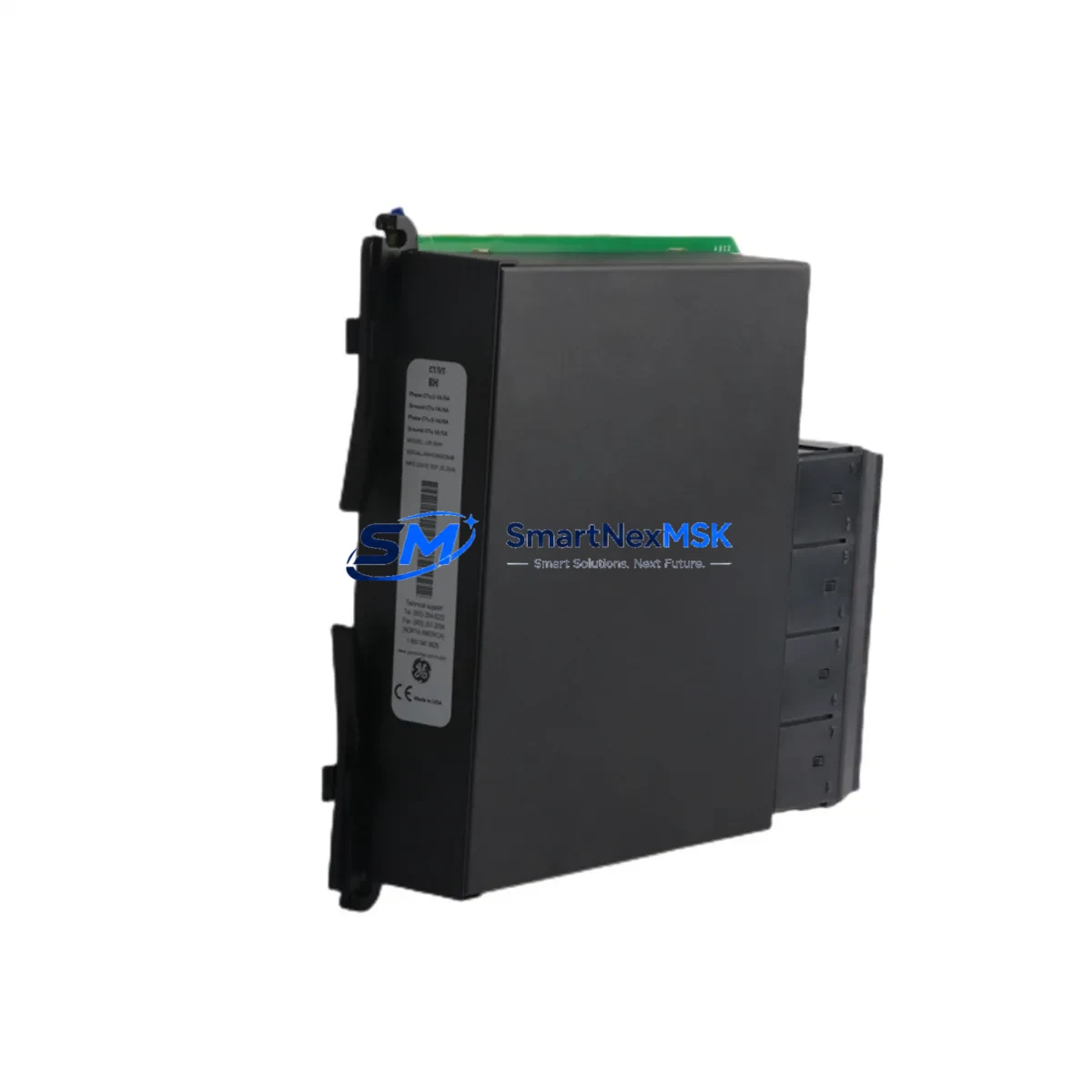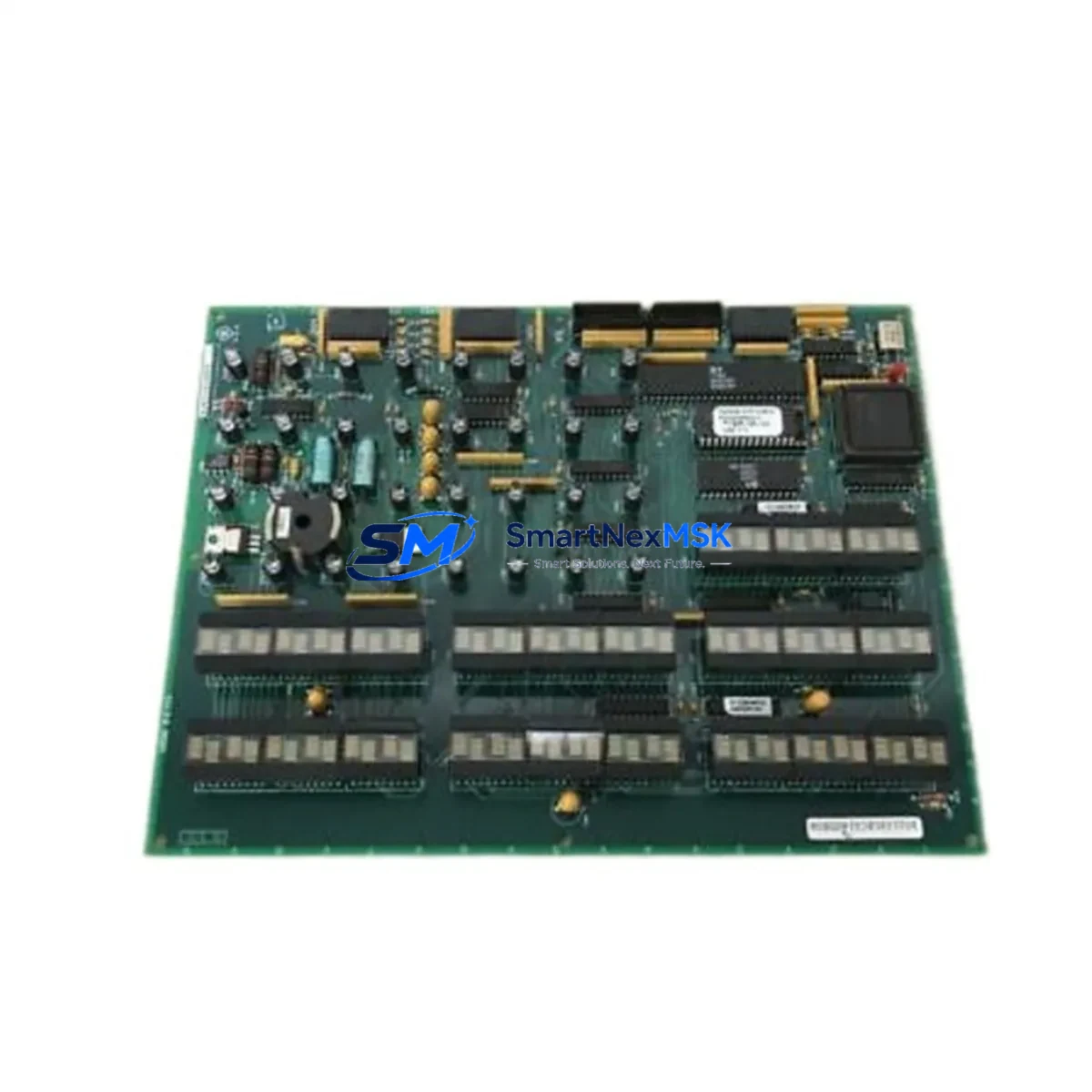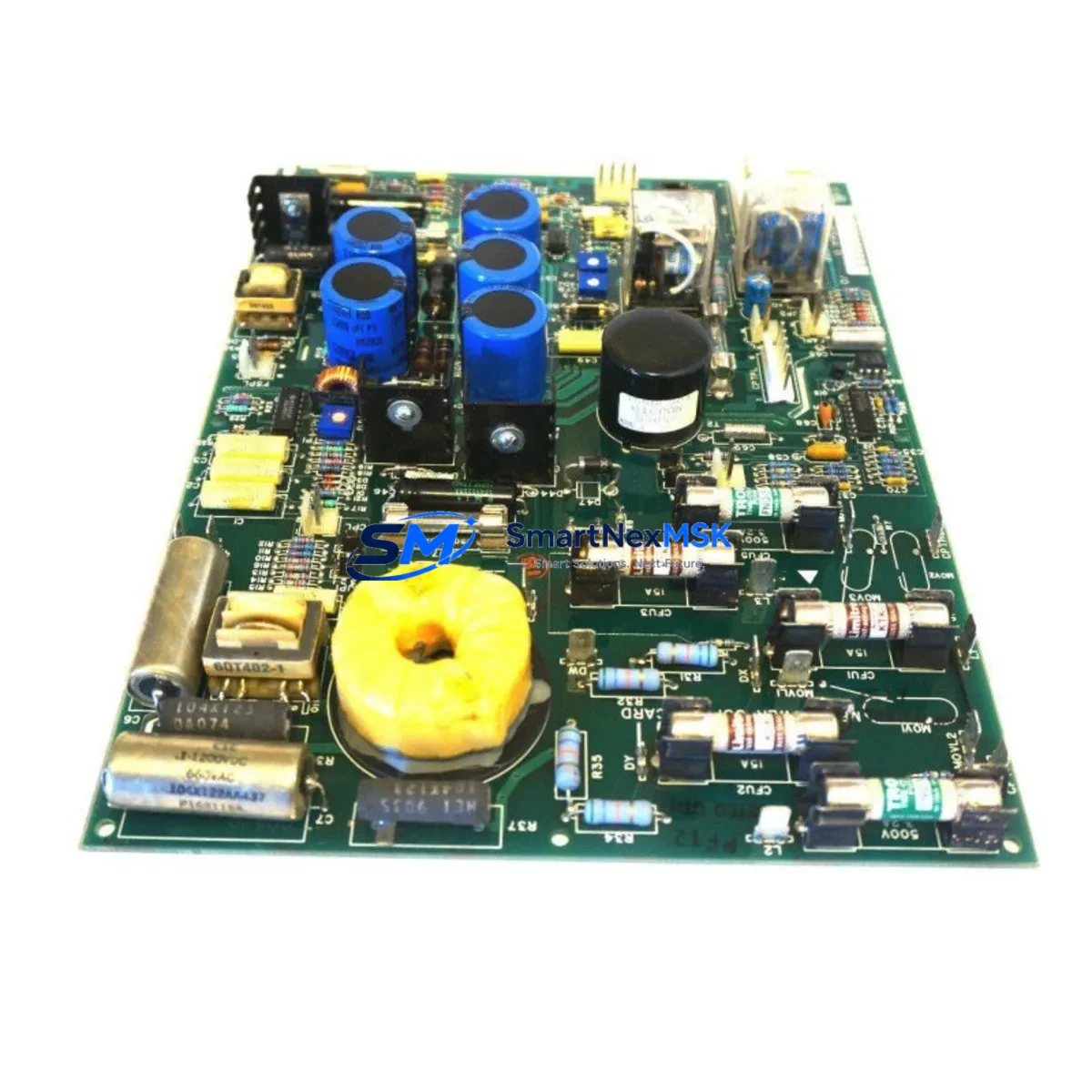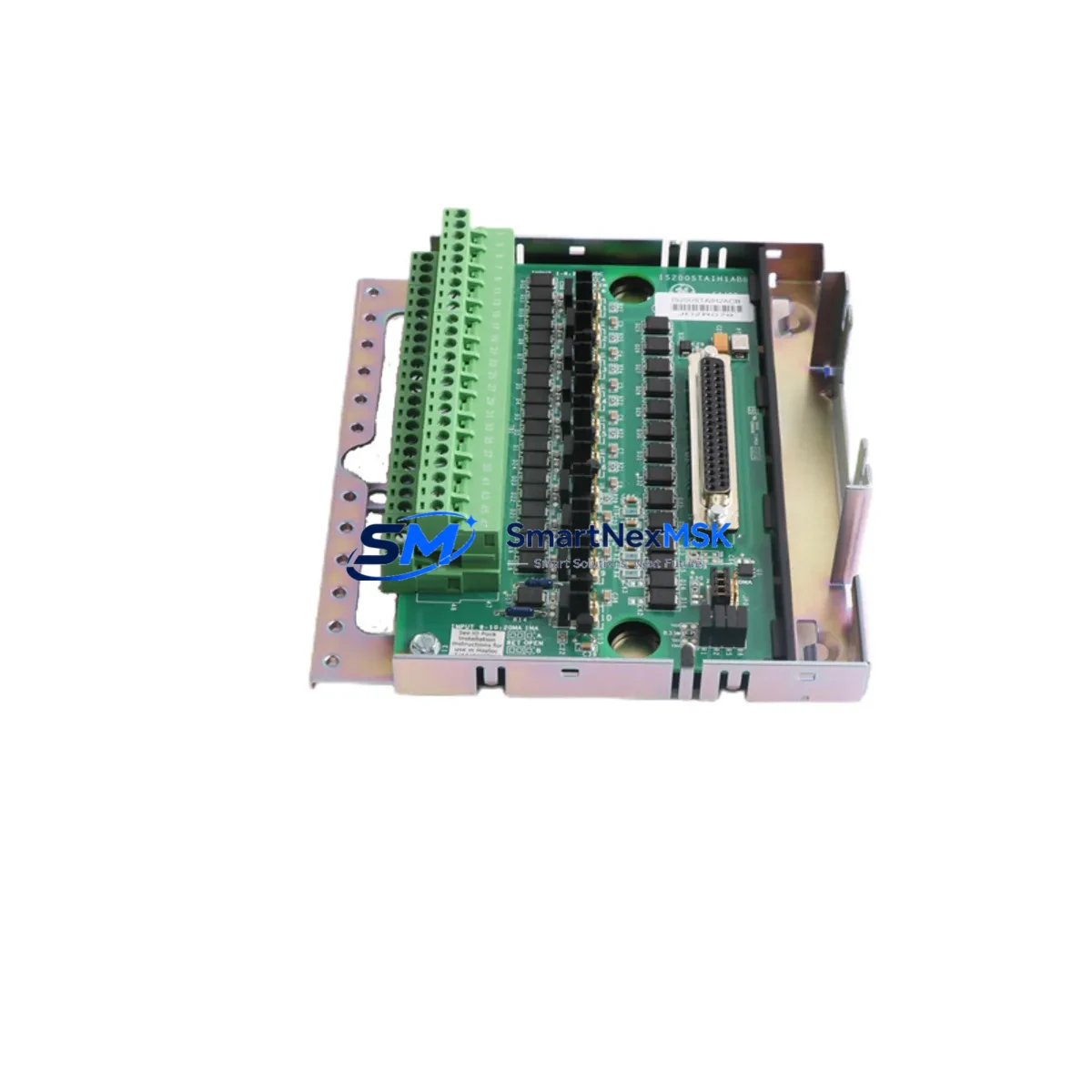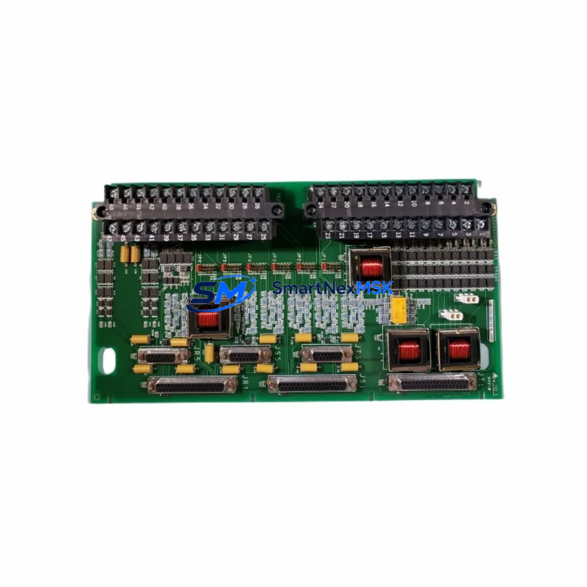
GE IS200TSVOH1B Retrofit-Ready Servo Termination Board for Mark VI Control Systems
The GE IS200TSVOH1B is a servo termination board engineered for the GE Mark VI turbine control platform, widely deployed across power generation, oil & gas, and heavy industrial facilities. As legacy Mark VI systems approach end-of-life and OEM support windows close, the IS200TSVOH1B has become a critical retrofit component for engineers tasked with sustaining servo-driven control loops without full system replacement. Whether you are replacing a failed board, upgrading a degraded servo interface, or migrating from an older Mark V configuration, this module provides a verified, drop-in compatible solution backed by a 12-month warranty.
Upgrade Compatibility Table
| Parameter | Details |
|---|---|
| Compatible Platform | GE Mark VI Turbine Control System |
| Replaces / Upgrades | IS200TSVOH1A, IS200TSVOH1C (earlier revisions); Mark V servo interface boards |
| Mounting / Installation | Standard Mark VI VME backplane; no mechanical modification required |
| Communication Compatibility | IONet (Ethernet-based Mark VI I/O network); compatible with IONET switch modules |
| Servo Interface | Dual-channel servo valve drive; compatible with LVDT feedback wiring |
| Terminal Wiring | Screw-terminal field wiring; verify existing cable harness pinout before installation |
| Replacement Recommendation | Direct board swap; re-use existing terminal blocks and field cables where possible |
| Commissioning Focus | LVDT calibration, servo loop tuning, I/O address verification in ToolboxST |
| Warranty | 12 months from date of shipment; covers manufacturing defects and functional failure |
Retrofit Planning for Existing Automation Systems
Successful integration of the IS200TSVOH1B into an operating Mark VI system requires careful pre-installation planning. Begin by auditing the existing IS200TSVOH1A or earlier revision currently installed in the VME rack. Confirm the backplane slot assignment and document the current I/O module address configured in ToolboxST, GE’s configuration and diagnostic software for the Mark VI platform. Mismatched module addresses are among the most common causes of post-swap communication faults.
Before powering down the turbine control cabinet, verify the PPRO (Protection, Primary, and Redundancy) controller status and ensure that the servo control loop can be safely placed in manual or bypass mode. In redundant Mark VI configurations, the IS215VCMIH2C VME communication module and associated IS200ERACH1A Ethernet relay adapter must remain online throughout the swap to maintain IONet continuity. Coordinate with the DCS operator to confirm that the HMI display — typically running GE’s Cimplicity SCADA or a third-party HMI — reflects the correct servo valve status before and after the replacement.
Field wiring to the IS200TSVOH1B connects via screw-terminal blocks. Retain the existing cable harness where possible, but verify each conductor against the original wiring diagram. Pay particular attention to the LVDT (Linear Variable Differential Transformer) feedback signal wiring: polarity reversal or incorrect excitation voltage will cause the servo loop to fault immediately on startup. If the existing IS200TBCIH1C terminal board is also degraded, replace it simultaneously to avoid a second outage window.
For sites migrating from a Mark V platform to Mark VI, the IS200TSVOH1B is part of a broader upgrade path that typically includes replacing the IS200DSPXH1D digital signal processor board, re-engineering the I/O map, and updating the application logic in ToolboxST. The IS200BICLH1C bus interface and clock module may also require replacement if the existing unit is not compatible with the target Mark VI firmware revision. Confirm firmware compatibility with GE Energy documentation before ordering.
Power supply capacity is another critical checkpoint. The Mark VI rack draws power from the IS200EPCTG1A power conditioner; adding or replacing servo termination boards can alter the total rack load. Verify that the existing power conditioner output is within specification after the new board is installed. If the rack is near its power budget limit, a IS200EPCTG1B or equivalent upgraded power conditioner should be sourced concurrently.
Downtime Control During System Migration
Minimizing unplanned downtime is the primary operational concern when replacing servo termination boards in a live turbine control environment. The recommended approach is to pre-configure and bench-test the IS200TSVOH1B before the scheduled maintenance window. Using a spare Mark VI rack or a ToolboxST offline configuration file, verify that the module address, I/O assignments, and servo loop parameters match the production system exactly. This eliminates configuration errors as a source of extended downtime during the live swap.
During the outage window, follow a structured sequence: isolate the servo valve, place the control loop in manual, remove the failed IS200TSVOH1B, install the replacement, restore power, and verify IONet communication before returning the loop to automatic. The entire process — when pre-planned — typically completes within a two-to-four hour maintenance window for a single servo channel. Retain the original application program backup from ToolboxST; do not rely solely on the controller’s onboard memory. If the IS215UCVEH2A UCVE controller card was also affected by the fault event, restore the program from the verified backup before re-enabling the servo loop.
Post-installation, perform a full LVDT calibration and servo valve stroke test before returning the turbine to service. Document all as-found and as-left measurements for the maintenance record. Our team provides pre-shipment functional testing on all IS200TSVOH1B units, with test reports available on request, to further reduce commissioning risk on site.
Retrofit Support FAQ
Q1: Is the IS200TSVOH1B a direct replacement for the IS200TSVOH1A?
Yes. The IS200TSVOH1B is a revision upgrade of the IS200TSVOH1A and is designed as a direct drop-in replacement within the same VME backplane slot. No mechanical or wiring changes are required in most installations. Confirm the firmware revision of your Mark VI controller in ToolboxST to ensure compatibility with the B-revision board before installation.
Q2: What commissioning steps are required after installation?
After physical installation, verify the module address in ToolboxST, confirm IONet communication status, perform LVDT zero and span calibration, and execute a servo valve stroke test. If the HMI displays a servo fault alarm after the swap, check the I/O address assignment and IONet switch connectivity before adjusting any control parameters.
Q3: Can this board be used in a Mark V to Mark VI migration project?
The IS200TSVOH1B is a Mark VI-native component and is not backward-compatible with Mark V racks. In a Mark V to Mark VI migration, the IS200TSVOH1B is installed in the new Mark VI VME rack as part of the upgraded servo interface layer. The Mark V servo termination wiring will require re-termination to match the Mark VI terminal block pinout.
Q4: What does the 12-month warranty cover?
All IS200TSVOH1B units supplied by SMARTNEXMSK carry a 12-month warranty from the date of shipment. The warranty covers manufacturing defects and functional failure under normal operating conditions. Pre-shipment functional testing is performed on every unit. Warranty claims are processed within 5 business days of receipt of the returned unit.
© 2026 SMARTNEXMSK. All rights reserved.
Original Source: https://smartnexmsk.com
Contact: [email protected] | +86 18259474341