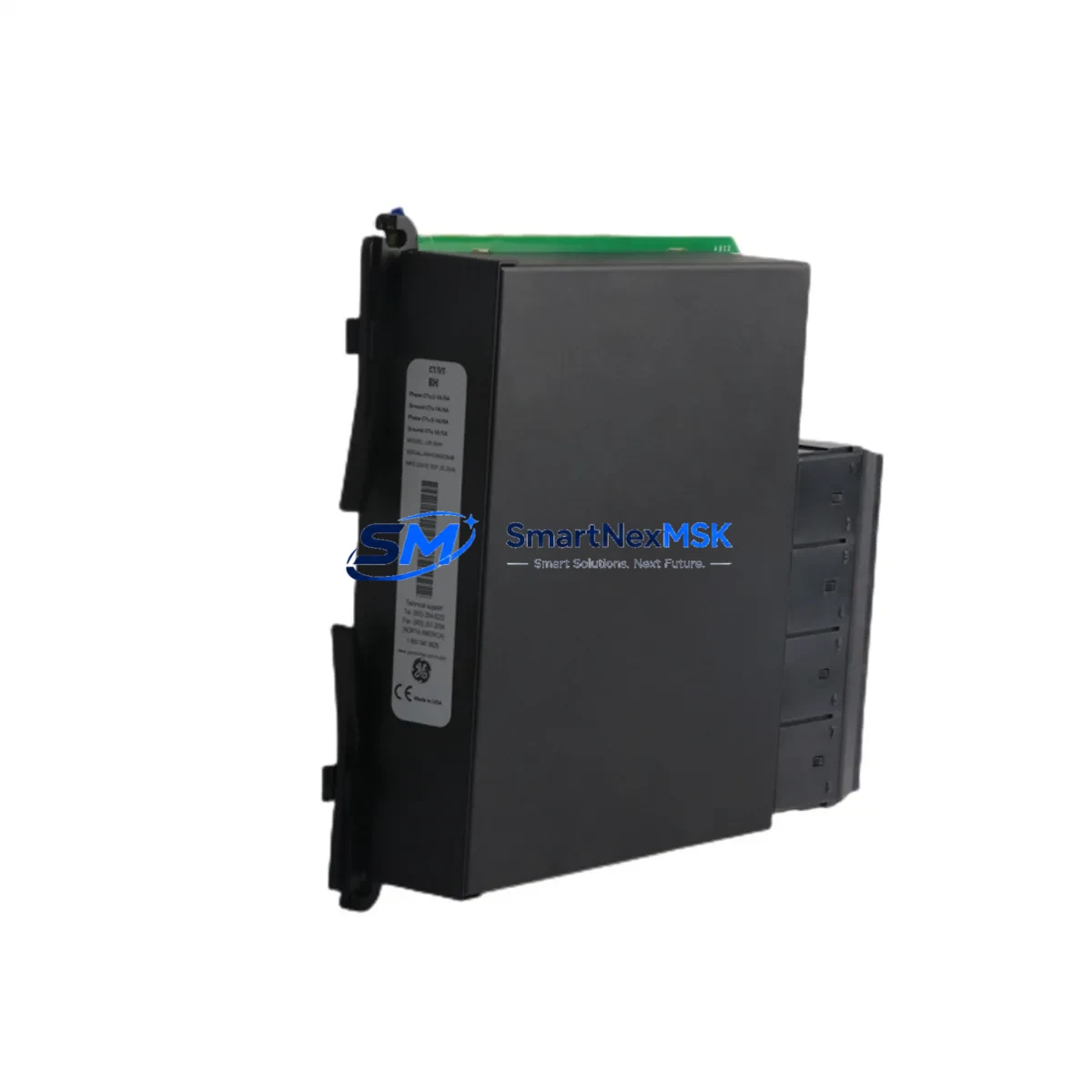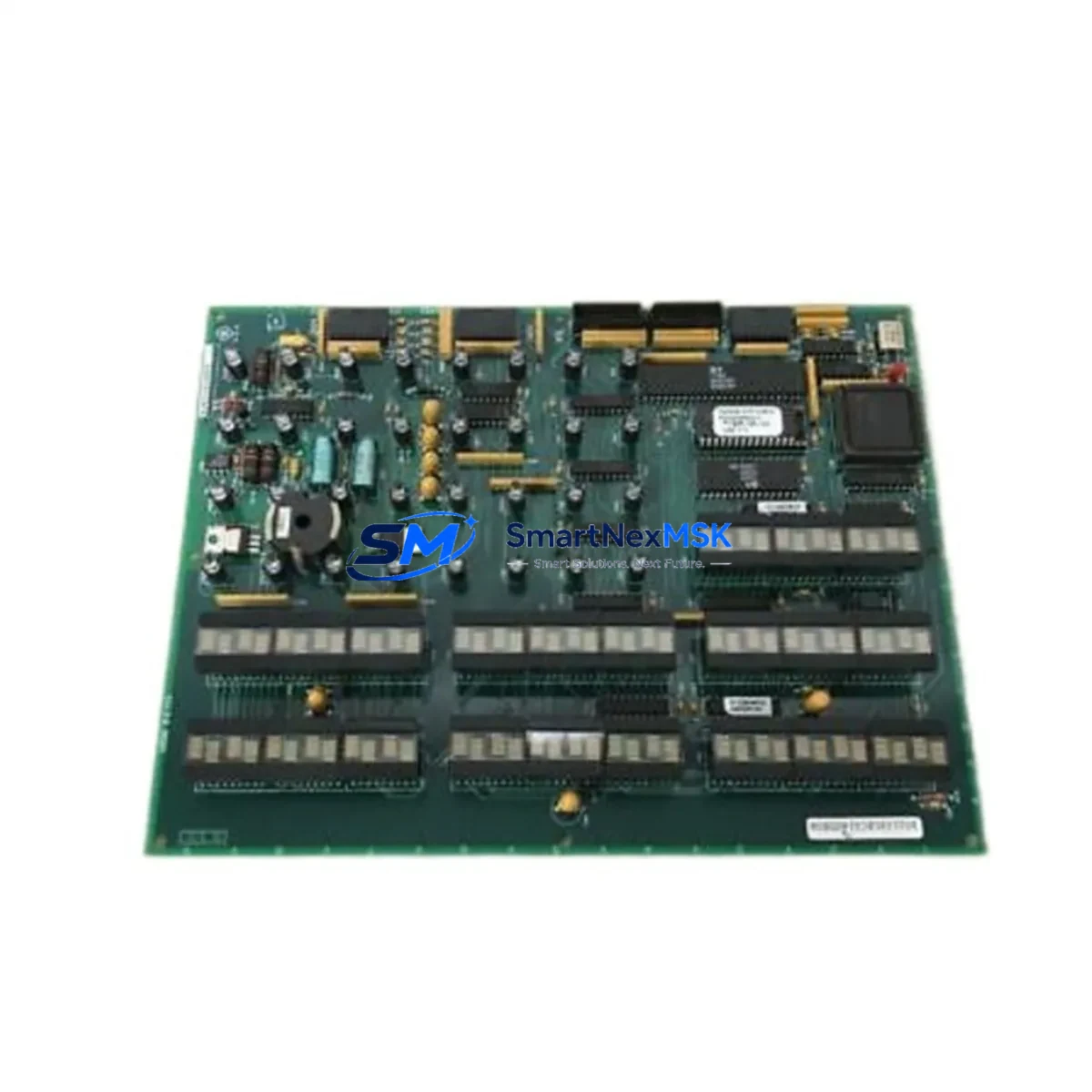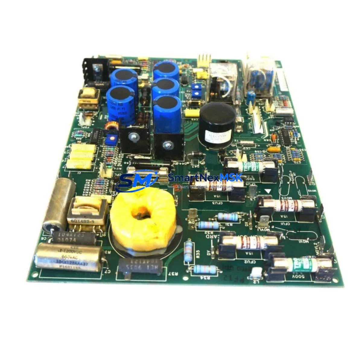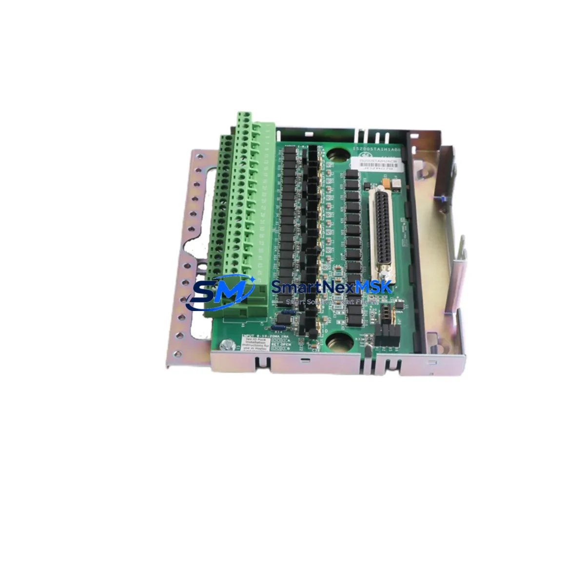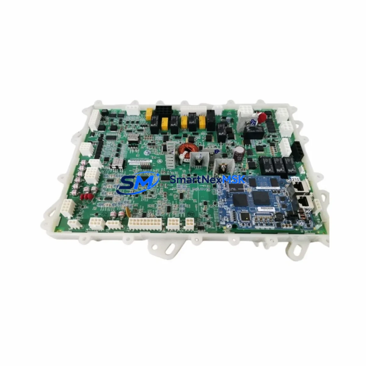
GE IS210BPPCH1AD Maintenance-Ready Spare for Mark VI Automation
The GE IS210BPPCH1AD is an original PCB control module designed for the GE Mark VI turbine control system — one of the most widely deployed distributed control architectures in power generation, oil & gas, and heavy industrial facilities worldwide. When this module fails or degrades, the consequences extend beyond a single I/O channel: the entire turbine control loop may be compromised, triggering unplanned shutdowns and costly downtime. Stocking a verified IS210BPPCH1AD spare is the single most effective step a maintenance team can take to protect system uptime and reduce mean time to repair (MTTR).
This unit is sourced as an original GE component, inspected for physical integrity, and functionally tested prior to shipment. Each IS210BPPCH1AD is dispatched with a 12-month warranty covering manufacturing defects and operational failures under normal service conditions. For maintenance engineers managing aging Mark VI cabinets, this module represents a direct, plug-compatible replacement that eliminates the need for firmware reconfiguration or hardware adaptation.
Spare Maintenance Table
| Parameter | Specification / Detail |
|---|---|
| Part Number | IS210BPPCH1AD |
| Manufacturer | General Electric (GE) |
| Series | Mark VI Turbine Control System |
| Module Type | PCB Control Module |
| Form Factor | Plug-in board, Mark VI backplane compatible |
| Power Supply Compatibility | Mark VI standard 28 VDC control power rail |
| I/O Interface | Integrated with Mark VI I/O terminal boards via backplane connector |
| Communication | IONet / Mark VI internal communication bus |
| Operating Temperature | 0°C to 60°C (standard industrial enclosure) |
| Mounting | Mark VI standard card cage / VME-style rack |
| Origin | United States |
| Condition | Original, tested before shipment |
| Warranty | 12 Months |
| Compatibility | GE Mark VI turbine control cabinets (VSVO, VTUR, VPRO, VCMI configurations) |
| Maintenance Recommendation | Replace as part of scheduled PCB module inspection cycle; verify backplane connector integrity before installation |
| Application Environment | Power generation, oil & gas, petrochemical, heavy industrial |
Maintenance Planning for Continuous Operation
Replacing the IS210BPPCH1AD in a live Mark VI cabinet is rarely an isolated task. Experienced maintenance engineers know that a PCB control module failure is often a symptom of broader stress in the control loop. Before returning the system to service, a structured inspection of adjacent components is essential to prevent repeat failures and ensure the replacement module operates within its rated parameters.
Begin with the Mark VI power supply modules — specifically the IS200EPCTG1A or equivalent EPCT power conditioner — to confirm that the 28 VDC control rail is stable and within tolerance. Voltage ripple or transient spikes are a leading cause of premature PCB module failure. Next, inspect the IS200TBCIH1C or IS200TBCIH1BAA terminal board connected to the IS210BPPCH1AD; damaged connector pins or corroded terminal blocks will cause intermittent I/O faults even after the control module is replaced.
Check the IS200VSVOH1B VSVO servo driver board if the turbine is experiencing valve positioning errors alongside the module fault — these two components share the same control loop in many Mark VI configurations. Similarly, the IS200VCMIH2C communication module should be inspected for IONet link integrity; a degraded communication module can generate false fault codes that implicate the IS210BPPCH1AD when the root cause lies upstream.
For cabinets with redundant I/O, verify the IS200TREGH1B or IS200TREGH1C relay output boards — relay contact wear is common in high-cycle applications and can mask control module performance issues during post-replacement testing. Inspect terminal strips and DIN rail-mounted fuse holders for signs of heat stress or loose terminations, particularly on the 24 VDC field power circuits feeding the I/O cards.
If the Mark VI cabinet includes an IS200DSPXH1D or IS200DSPXH1F DSP processor board, confirm that firmware versions are compatible with the replacement IS210BPPCH1AD revision level before commissioning. Mismatched firmware revisions are a documented source of post-replacement instability in Mark VI systems. Finally, review the IS200BIASH1B bias power supply board and any installed signal isolators on the 4–20 mA analog input circuits — degraded isolation can introduce ground loops that stress the new PCB module from the moment of installation.
Site Replacement Workflow
The IS210BPPCH1AD is designed for in-cabinet replacement without requiring specialized tooling, making it well-suited for emergency maintenance scenarios where minimizing downtime is the primary objective. The following workflow reflects best practices for Mark VI module replacement in operational industrial facilities.
Step 1 — Pre-replacement verification: Confirm the fault code logged by the Mark VI HMI (ToolboxST or equivalent) references the IS210BPPCH1AD slot address. Cross-reference with the cabinet wiring diagram to identify the exact card cage position. Do not assume slot location from fault description alone — Mark VI systems with redundant configurations may log faults on the primary module while the standby module has already taken control.
Step 2 — System state assessment: Determine whether the turbine can be safely transitioned to manual control or whether a controlled shutdown is required before module extraction. In simplex Mark VI configurations, hot-swap is not supported for PCB control modules; a controlled shutdown is mandatory. In TMR (Triple Modular Redundant) configurations, module replacement may be possible with the turbine online, subject to site safety procedures.
Step 3 — Module extraction and inspection: After de-energizing the relevant card cage slot (or completing the controlled shutdown), extract the IS210BPPCH1AD using the standard ejector levers. Inspect the backplane connector on both the module and the card cage for bent pins, corrosion, or debris. Clean with appropriate electronics-grade contact cleaner if required.
Step 4 — Replacement module installation: Insert the new IS210BPPCH1AD firmly until the ejector levers engage. Verify the module LED status indicators match the expected post-insertion state per the GE Mark VI System Guide. Re-energize the slot and monitor the HMI for fault clearance and I/O channel restoration.
Step 5 — Post-replacement functional test: Execute a full I/O channel scan from the ToolboxST engineering workstation. Verify analog input scaling, digital output response, and communication link status. Document the replacement in the site maintenance log with the new module serial number and installation date to support the 12-month warranty claim if required.
This workflow applies equally to legacy Mark VI installations where the IS210BPPCH1AD is being used to extend the operational life of a system that is no longer supported under a GE service contract. In these scenarios, maintaining a local spare inventory of two to three IS210BPPCH1AD units — alongside compatible terminal boards and power supply modules — is the most cost-effective strategy for sustaining system availability without committing to a full control system upgrade.
Spare Parts Support FAQ
Q1: Is the IS210BPPCH1AD compatible with all Mark VI cabinet configurations?
The IS210BPPCH1AD is compatible with standard GE Mark VI card cage configurations including VSVO, VTUR, VPRO, and VCMI cabinet types. Compatibility depends on the specific slot assignment defined in the Mark VI system configuration file. Before ordering, confirm the module revision level (suffix letter) matches or supersedes the revision currently installed in your cabinet. Our technical team can assist with revision compatibility verification prior to shipment.
Q2: What testing is performed before the IS210BPPCH1AD is shipped?
Each IS210BPPCH1AD undergoes a pre-shipment functional test that includes power-on self-test verification, backplane connector inspection, and visual PCB inspection for component damage, solder joint integrity, and corrosion. Units that do not pass all inspection criteria are not dispatched. A test report summary is available upon request for quality assurance documentation purposes.
Q3: How should the IS210BPPCH1AD be stored if purchased as a long-term spare?
Store the module in its original anti-static packaging in a climate-controlled environment: temperature 15°C to 35°C, relative humidity below 60% non-condensing. Avoid storage near strong magnetic fields or in environments with airborne contaminants. Inspect the module annually for any signs of component degradation. The 12-month warranty period begins from the date of shipment, not the date of installation, so plan procurement timing accordingly for long-term spare inventory strategies.
Q4: Can the IS210BPPCH1AD be used to replace an older revision of the same module?
In most cases, later revision IS210BPPCH1AD units are backward compatible with earlier revision installations. However, GE Mark VI systems with specific firmware versions may require a matching or minimum module revision. We recommend providing your current module revision and Mark VI firmware version when placing your order so our team can confirm compatibility before shipment. This eliminates the risk of a revision mismatch causing post-installation faults.
© 2026 SMARTNEXMSK. All rights reserved.
Original Source: https://smartnexmsk.com
Contact: [email protected] | +86 18259474341