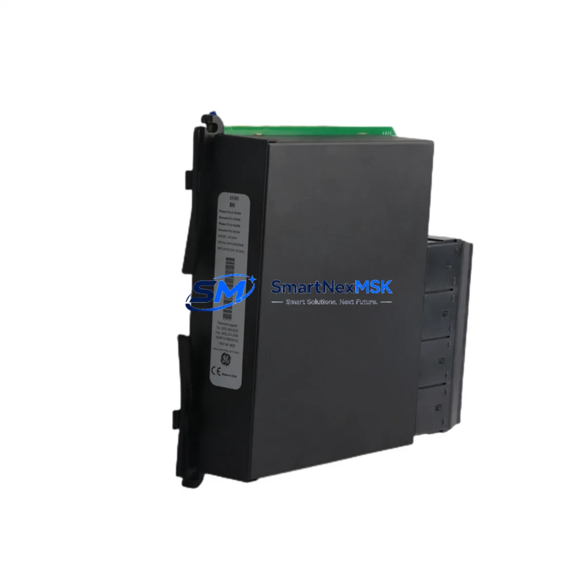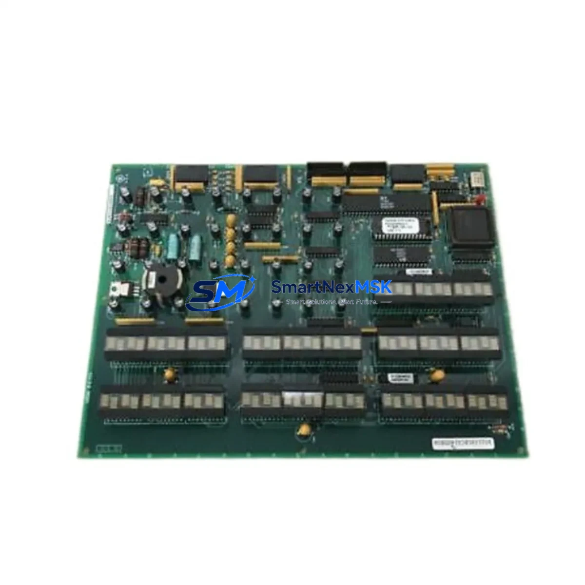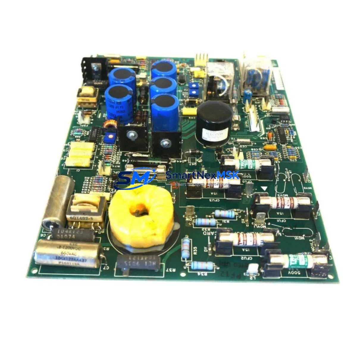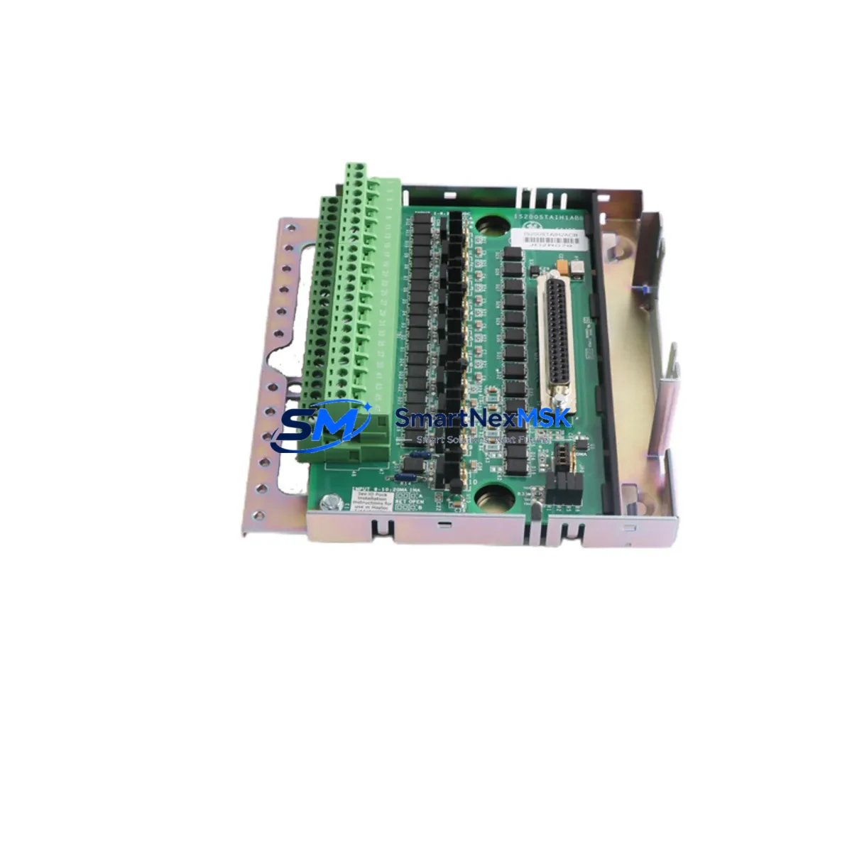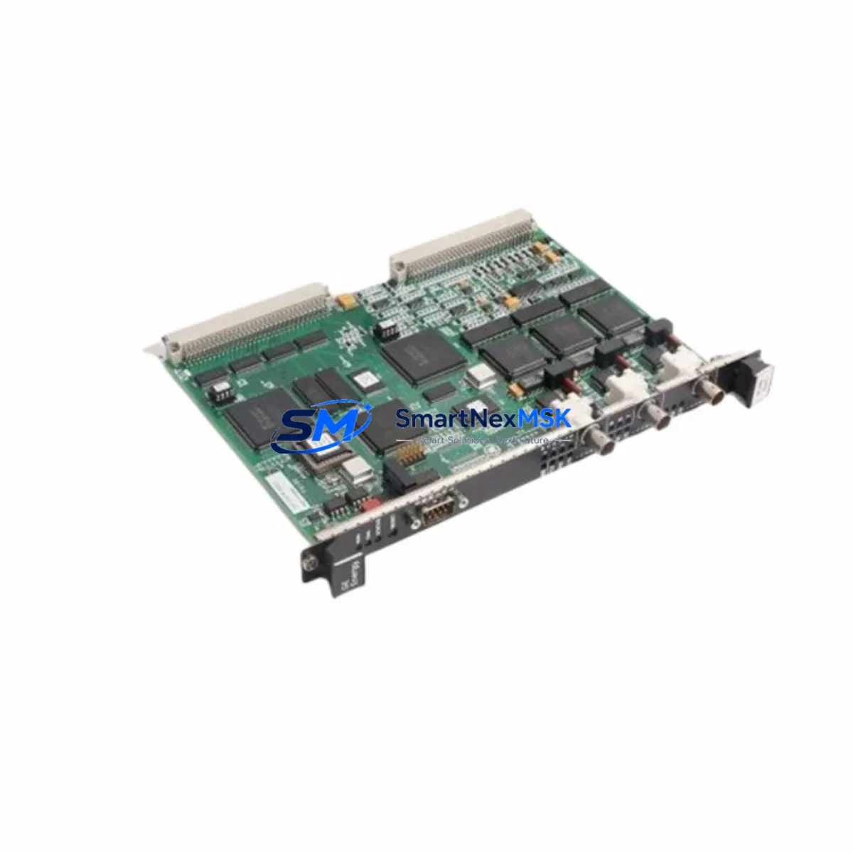
GE IS215UCUEH2AB Retrofit-Ready UCU for Mark VIe Control Systems: Seamless Compatibility Upgrade for Legacy Automation
The GE IS215UCUEH2AB is a Unit Control Unit (UCU) board designed for the GE Mark VIe Distributed Control System, widely deployed in gas turbine, steam turbine, and combined-cycle power generation facilities. As legacy Mark V and Mark VI platforms approach end-of-life and OEM support windows close, the IS215UCUEH2AB has become a critical retrofit component for engineers managing aging control infrastructure. This board serves as a direct replacement for failed or obsolete UCU modules, enabling facilities to extend operational life without committing to a full DCS overhaul.
Whether you are executing a planned control system modernization, responding to an unplanned module failure, or building a strategic spare-parts inventory, the IS215UCUEH2AB provides a verified, in-stock solution with a 12-month warranty and documented compatibility across the Mark VIe platform family.
Upgrade Compatibility Table
| Parameter | IS215UCUEH2AB Specification | Retrofit Notes |
|---|---|---|
| Compatible Platform | GE Mark VIe DCS | Also applicable in Mark VIeS simplex configurations |
| Module Function | Unit Control Unit (UCU) — primary controller board | Replaces failed or end-of-life UCU in existing rack |
| Backplane Interface | Mark VIe standard VME-style backplane connector | Verify backplane revision before installation; IS200 series racks are compatible |
| Communication Protocol | IONet Ethernet (100 Mbps), ARCNET legacy support | Confirm IONet switch configuration; replace IS215ENET boards if upgrading from ARCNET |
| Power Supply Requirement | +5 VDC, +/-15 VDC via backplane | Verify IS200EPSMG or equivalent power supply capacity before swap |
| Installation Format | Single-slot VME board, front-access terminal | No mechanical modification required for standard Mark VIe enclosures |
| Firmware Compatibility | Compatible with ToolboxST configuration software | Re-download application code via ToolboxST after board swap |
| Replacement Path | Direct drop-in for IS215UCUEH2AB variants (suffix A/B) | Cross-reference IS215UCUEH1AB for earlier hardware revision |
| Commissioning Requirement | ToolboxST download + I/O force check + trip test | Coordinate with control room for safe-state entry before live swap |
| Warranty | 12-Month Warranty — covers manufacturing defects and functional failure under normal operating conditions | |
Retrofit Planning for Existing Automation Systems
Replacing the IS215UCUEH2AB in an operating Mark VIe system requires careful pre-planning across multiple subsystems. The UCU board is the central processing unit of the Mark VIe controller rack, coordinating I/O data acquisition, control algorithm execution, and communication with the HMI and historian. A poorly planned swap can result in extended downtime, loss of program logic, or communication faults that cascade across the control network.
Power and Backplane Verification: Before removing the existing UCU, confirm that the rack’s power supply — typically an IS200EPSMG power supply module — is delivering stable +5 VDC and ±15 VDC rails. Voltage sag under load is a common cause of UCU instability that is misdiagnosed as board failure. If the power supply is also aging, consider replacing it concurrently with the UCU to avoid a repeat outage.
I/O Module Inventory: Document all I/O modules installed in the same rack, including IS200VTURH1B turbine I/O boards, IS215VPROH1B protection modules, and any IS200TREGH1B terminal boards connected via ribbon cable. Verify that each module’s firmware revision is compatible with the replacement UCU’s application code version. Mismatched firmware between the UCU and I/O modules is a leading cause of post-swap communication errors.
Communication Network Preparation: The Mark VIe UCU communicates with the HMI workstation and historian via IONet — a dedicated 100 Mbps Ethernet network. Before the swap, confirm that the IS215ENET Ethernet communication board in the rack is functional and that the IONet switch port assignments are documented. If the facility is migrating from an older ARCNET-based Mark VI system, the IS215UCUEH2AB supports IONet natively, but the IS200AEPAH1A ARCNET interface board must be removed and the network topology updated accordingly.
HMI and Historian Continuity: Coordinate with the HMI team to ensure that the GE Cimplicity HMI or third-party SCADA screens referencing the UCU’s tag database are not disrupted during the swap. Export the current ToolboxST project file and back up the historian configuration before beginning work. After the new UCU is installed and the application code is downloaded, verify that all dynamic tags are updating correctly on the HMI before releasing the unit to operations.
Terminal and Wiring Checks: For systems using IS200TBCIH1C terminal board assemblies or IS200TTURH1C turbine terminal boards, inspect all field wiring terminations for corrosion, loose screws, and correct wire routing before powering up the new UCU. Wiring faults that were masked by a failing UCU will immediately surface as I/O alarms after the replacement board is commissioned.
Spare Parts Strategy: Facilities managing multiple Mark VIe controllers should consider stocking a minimum of one spare IS215UCUEH2AB per control system, alongside spares for the IS215VPROH1B protection module and the IS200EPSMG power supply. For sites with aging IS215UCUEH1AB (earlier hardware revision), the H2AB suffix represents a compatible upgrade path that does not require rack or wiring modifications.
Downtime Control During System Migration
Minimizing downtime during a UCU replacement on an operating Mark VIe system requires a structured approach that protects program logic, preserves field wiring integrity, and maintains communication continuity throughout the swap window.
Pre-Outage Preparation (48–72 Hours Before): Export the complete ToolboxST project from the existing UCU and store it on a secure engineering workstation. Verify that the backup copy loads without errors and that all I/O assignments, control constants, and alarm setpoints are intact. Prepare the replacement IS215UCUEH2AB by confirming its hardware revision and performing a bench power-on test if possible. Stage all tools, including the ToolboxST programming cable, a laptop with the correct software version, and a multimeter for voltage verification.
Safe-State Entry: Coordinate with operations to bring the controlled process to a safe state — for turbine applications, this typically means a controlled shutdown and lockout/tagout of the fuel supply. Do not attempt a hot-swap of the UCU board without explicit OEM guidance, as the Mark VIe UCU does not support live replacement in standard simplex configurations. In TMR (Triple Modular Redundant) configurations, consult the system integrator before proceeding, as the replacement procedure differs significantly.
Board Swap and Download: Remove the failed UCU by releasing the front-panel ejector levers and sliding the board out of the VME backplane. Install the replacement IS215UCUEH2AB, ensuring full backplane connector engagement. Power up the rack and confirm that the UCU’s status LEDs indicate a healthy boot sequence before connecting the ToolboxST programming cable. Download the application code, verify I/O forcing is cleared, and perform a complete I/O check against the field wiring documentation.
Return to Service: After the I/O check is complete, perform a controlled trip test to verify that the protection logic — including overspeed, overtemperature, and vibration trips — is functioning correctly. Confirm that the HMI is receiving live data from all UCU-managed tags and that the historian is logging correctly. Document the swap in the maintenance management system, including the replaced board’s serial number, the new board’s serial number, and the ToolboxST project version used.
With proper preparation, a Mark VIe UCU replacement can typically be completed within a 4–8 hour maintenance window, significantly reducing the revenue impact of an unplanned outage.
Retrofit Support FAQ
Q1: Is the IS215UCUEH2AB a direct drop-in replacement for the IS215UCUEH1AB?
In most cases, yes. The H2AB suffix indicates a later hardware revision of the same UCU board family. The backplane connector, slot dimensions, and ToolboxST software interface are identical. However, you should verify that your ToolboxST project was compiled with a software version compatible with the H2AB hardware revision. If you are unsure, contact our technical team with your current ToolboxST version number before ordering.
Q2: What commissioning steps are required after installing the replacement board?
After physical installation, connect a ToolboxST-compatible programming cable to the UCU’s front-panel Ethernet port and download the backed-up application code. Clear any I/O forces that may have been set during troubleshooting, perform a full I/O scan to verify field signal integrity, and execute a controlled trip test to confirm protection logic. For IONet-connected systems, verify that the UCU’s IP address assignment matches the network configuration documented in the ToolboxST project.
Q3: How do I verify wiring compatibility before installing the IS215UCUEH2AB?
The IS215UCUEH2AB connects to the field via terminal boards — typically IS200TBCIH1C or IS200TTURH1C assemblies — using pre-wired ribbon cable harnesses. These harnesses do not need to be modified for a like-for-like UCU replacement. Before installation, inspect all ribbon cable connectors for bent pins or corrosion, and verify that the terminal board screws are torqued to specification. If the system uses direct-wired I/O modules such as the IS200VTURH1B, check each field terminal for correct wire seating.
Q4: What does the 12-month warranty cover, and what is the return process?
The 12-month warranty covers manufacturing defects and functional failures under normal operating conditions, including board-level component failures and firmware corruption. It does not cover damage caused by incorrect installation, overvoltage, or physical impact. To initiate a warranty claim, contact our sales team with the board’s serial number, a description of the failure symptom, and your original order reference. We will arrange return shipping and provide a replacement or repaired unit within the agreed lead time.
© 2026 SMARTNEXMSK. All rights reserved.
Original Source: https://smartnexmsk.com
Contact: [email protected] | +86 18259474341