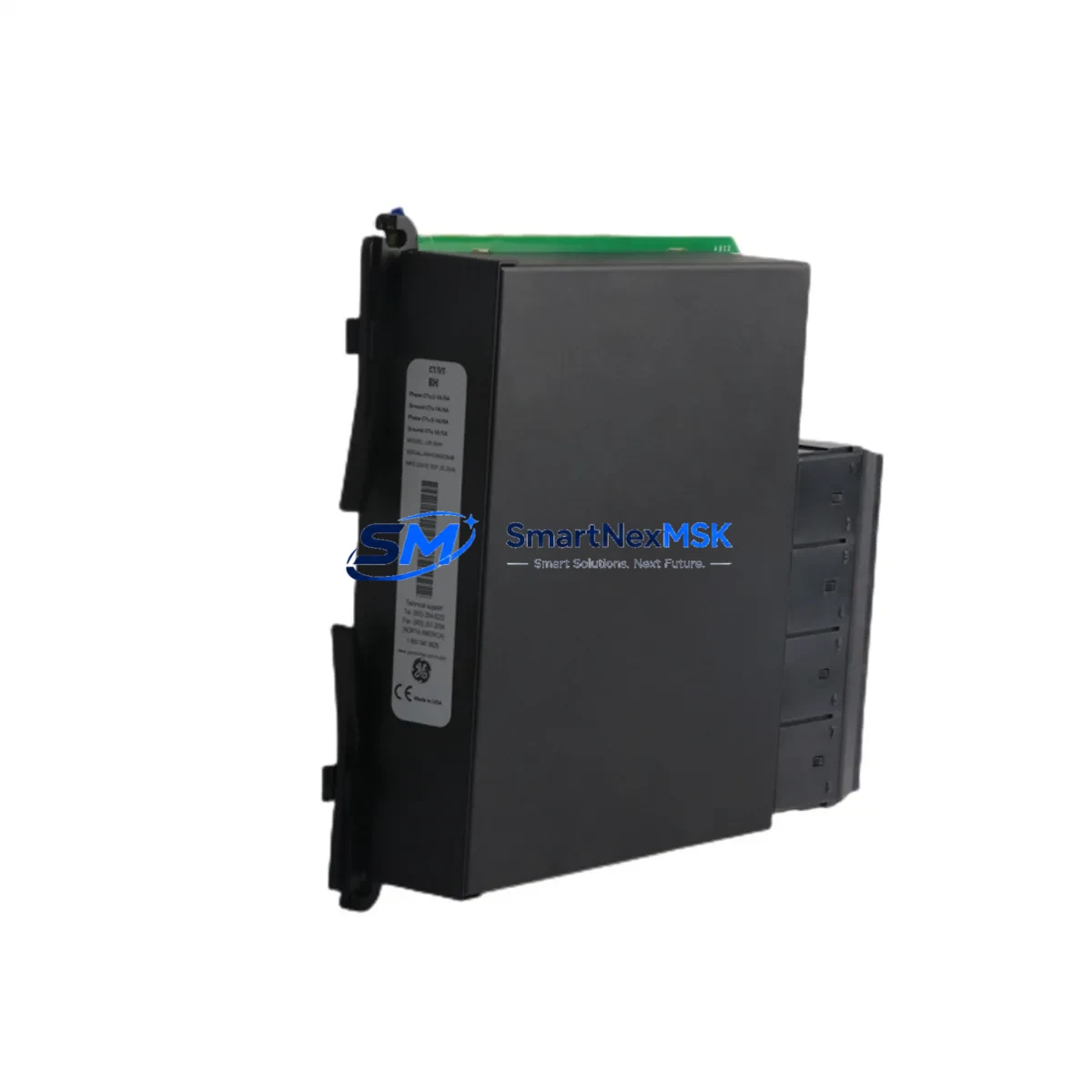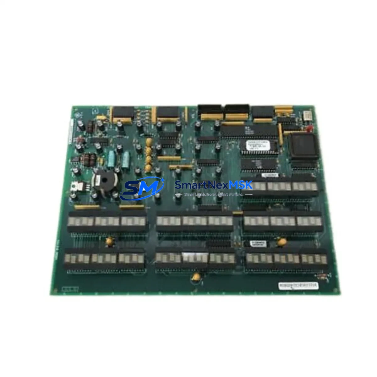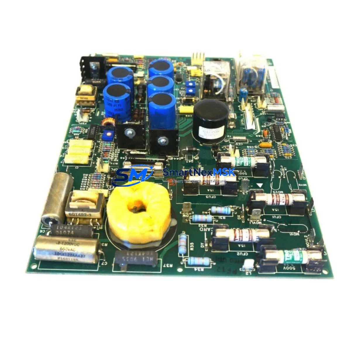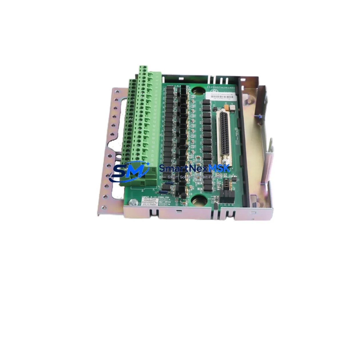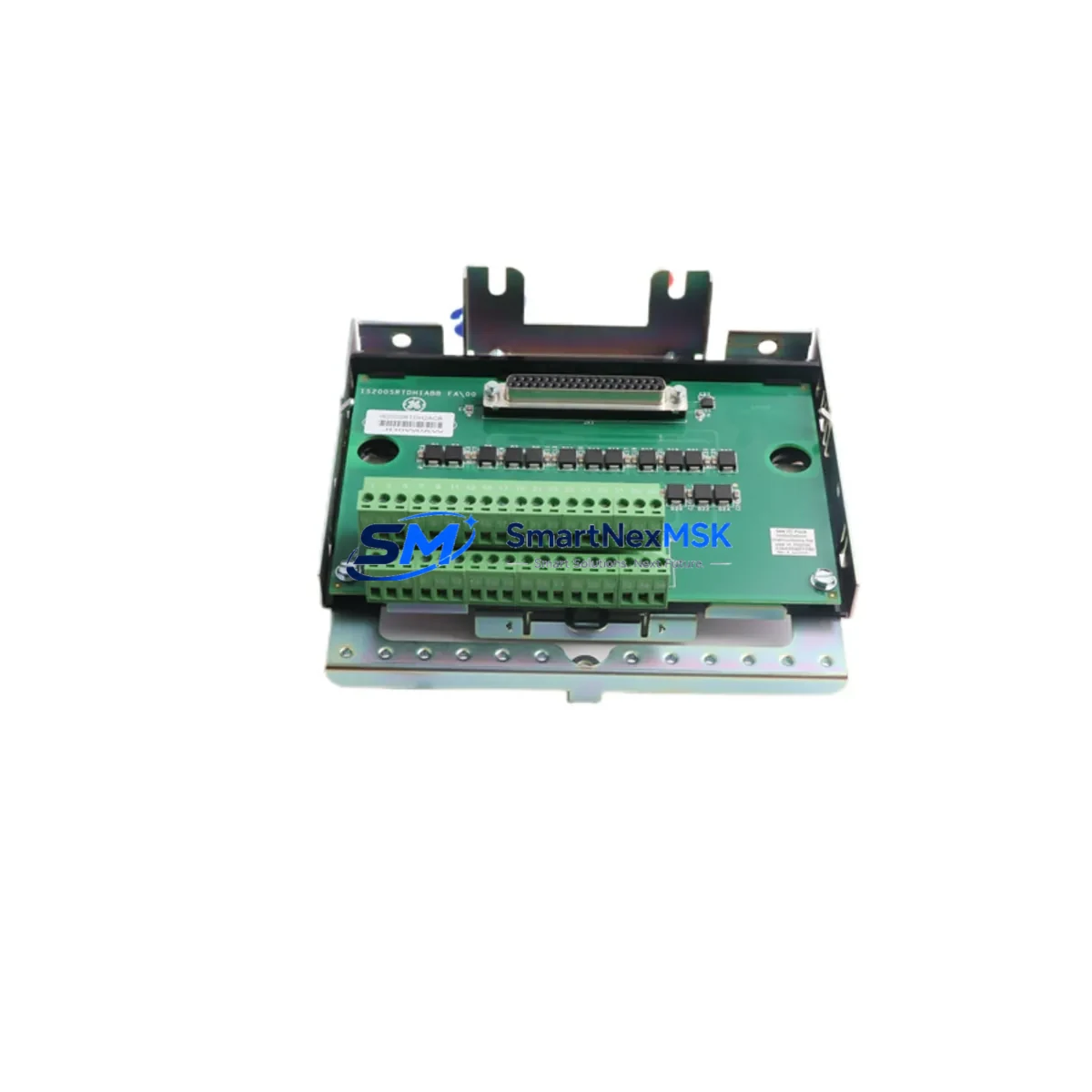
GE IS230SNRTH2A Retrofit-Ready RTD Input for Mark VI Control Systems
The GE IS230SNRTH2A is a high-reliability RTD (Resistance Temperature Detector) input module engineered for GE’s Mark VI turbine control platform. Designed as a retrofit-ready replacement for legacy RTD input cards — most notably the IS200SRTDH2ACB — this module enables plant engineers and system integrators to modernize aging control architectures without requiring full platform migration. Whether you are managing a gas turbine, steam turbine, or combined-cycle unit, the IS230SNRTH2A delivers the signal conditioning accuracy and backplane compatibility required for continuous, uninterrupted operation.
At SMARTNEXMSK, every IS230SNRTH2A unit is sourced from verified supply channels, subjected to pre-shipment functional testing, and backed by a 12-month warranty. Inventory is maintained in-stock to support urgent retrofit and emergency replacement requirements globally.
Upgrade Compatibility Table
| Parameter | IS230SNRTH2A (Replacement) | IS200SRTDH2ACB (Legacy) |
|---|---|---|
| Module Type | RTD Input, Mark VI Series | RTD Input, Mark VI Series |
| Backplane Interface | Mark VI VME-style backplane | Mark VI VME-style backplane |
| RTD Input Channels | Up to 16 channels (configurable) | Up to 16 channels |
| Supported RTD Types | PT100, PT1000, Ni120, Cu10 | PT100, PT1000 |
| Communication Protocol | IONet / Mark VI internal bus | IONet / Mark VI internal bus |
| Terminal Block Wiring | Compatible with existing TB wiring | Standard Mark VI TB layout |
| Rack / Chassis Fit | Mark VI R, S, T rack — direct fit | Mark VI R, S, T rack |
| Firmware / Toolbox | GE ToolboxST compatible | GE ToolboxST compatible |
| Replacement Recommendation | Direct drop-in; address re-mapping may apply | — |
| Commissioning Focus | Channel calibration, loop check, alarm setpoints | — |
| Warranty | 12 Months | OEM — typically expired |
Retrofit Planning for Existing Automation Systems
Replacing the IS230SNRTH2A — or its predecessor IS200SRTDH2ACB — within an operating Mark VI turbine control system requires careful pre-engineering to avoid unplanned downtime and configuration drift. The following planning checklist reflects the real-world steps that instrumentation engineers and DCS integrators follow during a controlled retrofit.
Power Budget Verification: Before installation, confirm that the Mark VI power supply module — typically a IS200EPCTG1A or equivalent EPCT-series card — has sufficient headroom to support the IS230SNRTH2A alongside co-installed I/O modules. Overloaded power rails are a common root cause of intermittent faults in aging control cabinets.
Terminal Block and Wiring Audit: The IS230SNRTH2A uses the same Mark VI terminal board layout as the IS200SRTDH2ACB. However, field wiring should be audited against the original loop drawings. Pay particular attention to 2-wire versus 3-wire RTD configurations — incorrect wiring will introduce lead resistance errors that affect temperature accuracy. Confirm that the IS200TBCIH2C or equivalent terminal board is correctly seated and that all shield grounds are intact.
Backplane Slot and Module Address: In a Mark VI R-type or S-type rack, each slot carries a fixed I/O address recognized by the VCMI (VME Communication Module Interface) or the IS215VCMIH2C controller card. When swapping the RTD module, verify that the slot address in GE ToolboxST matches the physical slot. Mismatched addresses will cause the controller to report a hardware fault and may trigger a turbine trip if the system is in service.
Program and Configuration Compatibility: Export and archive the current ToolboxST project before any hardware change. The IS230SNRTH2A is recognized by ToolboxST as a compatible replacement; however, if the firmware revision differs from the original card, a partial download may be required. Coordinate with the site controls engineer to schedule the download during a planned outage window. Confirm that HMI faceplates — whether running on a Cimplicity workstation or a third-party SCADA — correctly reflect the updated I/O tag assignments after the download.
Communication Link Integrity: The Mark VI IONet is a deterministic Ethernet-based control network. After module replacement, verify that the IONet switch — often a IS200IOCIH1A or managed industrial Ethernet switch — correctly enumerates the new module. Use the ToolboxST diagnostics view to confirm that all RTD channels are reporting valid process values before returning the unit to automatic control.
I/O Expansion Considerations: If the retrofit is part of a broader I/O expansion — for example, adding new thermocouple or analog input points — consider whether additional IS230SNAOH2A analog output modules or IS230SDOAH2A digital output modules are required in adjacent slots. Plan rack space and power allocation accordingly before ordering.
Pre-Shipment Testing: Every IS230SNRTH2A shipped by SMARTNEXMSK undergoes bench-level functional verification, including channel-by-channel RTD simulation across the full temperature range. A test report is available upon request. Units are packed in anti-static ESD bags with foam cushioning to prevent transit damage to the backplane connector pins.
Downtime Control During System Migration
Minimizing turbine or process downtime during a Mark VI RTD module replacement requires a structured migration approach. The following practices are recommended by experienced controls engineers working on GE Frame 6, Frame 7, and Frame 9 gas turbine fleets, as well as steam turbine and compressor train applications.
Hot-Standby Preparation: Where the Mark VI is configured in TMR (Triple Modular Redundant) or dual-redundant mode, the IS230SNRTH2A can often be replaced in one voting leg while the remaining legs maintain control. Confirm the voting logic configuration in ToolboxST before proceeding. In simplex configurations, a planned outage window is required.
Program Logic Preservation: Never perform a full download during live operation. Use the ToolboxST “partial download” function to push only the I/O configuration changes associated with the new module. This preserves all running setpoints, PID tuning parameters, alarm limits, and sequence logic in the IS215VCMIH2C controller without interrupting the control scan cycle.
Loop Check and Calibration: After physical installation, perform a channel-by-channel loop check using a precision RTD simulator. Verify that each channel’s engineering unit reading in the HMI matches the simulated input within the specified accuracy band (typically ±0.5°C for PT100 inputs). Document all as-found and as-left readings in the site calibration record.
Alarm and Trip Setpoint Verification: Confirm that all high-temperature alarms, shutdown setpoints, and rate-of-change limits associated with the replaced RTD channels are correctly configured in ToolboxST and reflected in the HMI alarm summary. A missed setpoint during commissioning is a common cause of nuisance trips in the days following a module replacement.
Return to Service Checklist: Before releasing the unit to automatic operation, complete a formal return-to-service checklist covering: module LED status (all green), IONet communication confirmed, all RTD channels in scan, HMI values stable, no active hardware faults in the ToolboxST diagnostics view, and site supervisor sign-off. SMARTNEXMSK can provide a standard commissioning checklist template upon request.
Retrofit Support FAQ
Q1: Is the IS230SNRTH2A a direct drop-in replacement for the IS200SRTDH2ACB?
In most Mark VI installations, yes. Both modules occupy the same backplane slot, use the same terminal board wiring layout, and are recognized by GE ToolboxST as equivalent RTD input cards. A partial ToolboxST download is typically required to update the I/O configuration. Module address re-mapping may be needed if the physical slot position has changed. SMARTNEXMSK’s technical team can assist with pre-installation compatibility verification at no charge.
Q2: What commissioning steps are required after installation?
After seating the IS230SNRTH2A in the rack, perform the following: (1) confirm IONet communication in ToolboxST diagnostics, (2) execute a partial download to push the updated I/O configuration, (3) perform a channel-by-channel RTD loop check with a calibrated simulator, (4) verify HMI tag values and alarm setpoints, and (5) complete the return-to-service checklist. Total commissioning time for an experienced controls technician is typically 2–4 hours per module in a planned outage scenario.
Q3: How do I verify wiring compatibility with my existing terminal board?
The IS230SNRTH2A is designed for use with standard Mark VI terminal boards such as the IS200TBCIH2C. Compare your existing loop drawings against the IS230SNRTH2A wiring diagram (available in the GE Mark VI I/O Module Reference Manual). Pay particular attention to RTD wire configuration (2-wire, 3-wire, or 4-wire) and confirm that shield drain wires are terminated at the correct ground point on the terminal board.
Q4: What does the 12-month warranty cover?
SMARTNEXMSK’s 12-month warranty covers manufacturing defects, functional failures under normal operating conditions, and any faults identified during the pre-shipment test that were not disclosed at the time of sale. The warranty period begins from the date of shipment. In the event of a warranty claim, SMARTNEXMSK will provide a replacement unit or full refund at our discretion. Warranty does not cover damage resulting from incorrect installation, overvoltage, or physical mishandling. All warranty claims are processed within 5 business days.
© 2026 SMARTNEXMSK. All rights reserved.
Original Source: https://smartnexmsk.com
Contact: [email protected] | +86 18259474341