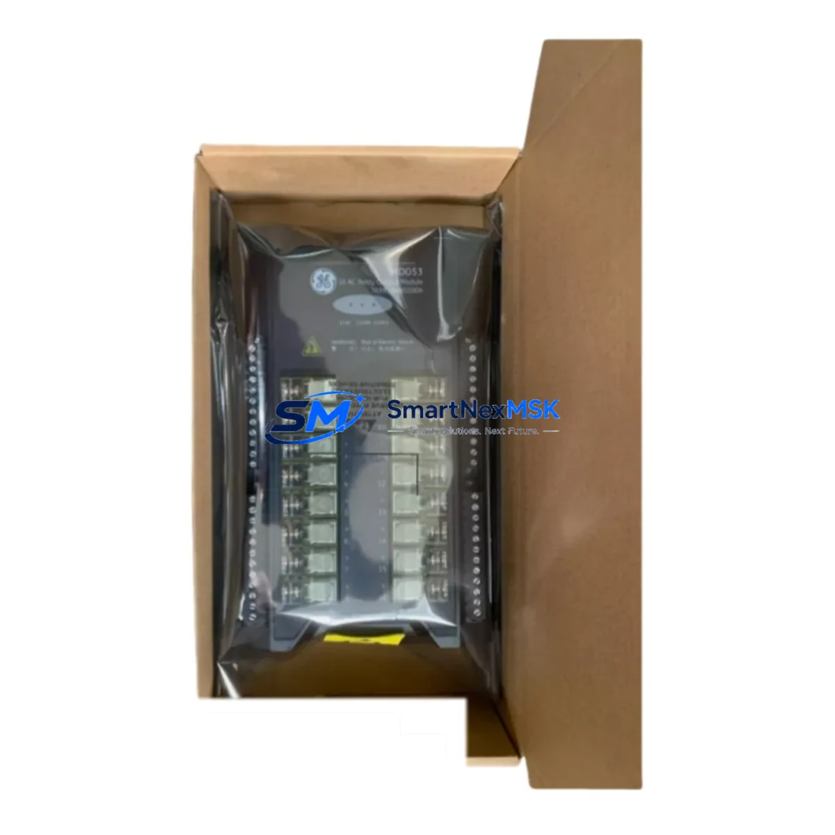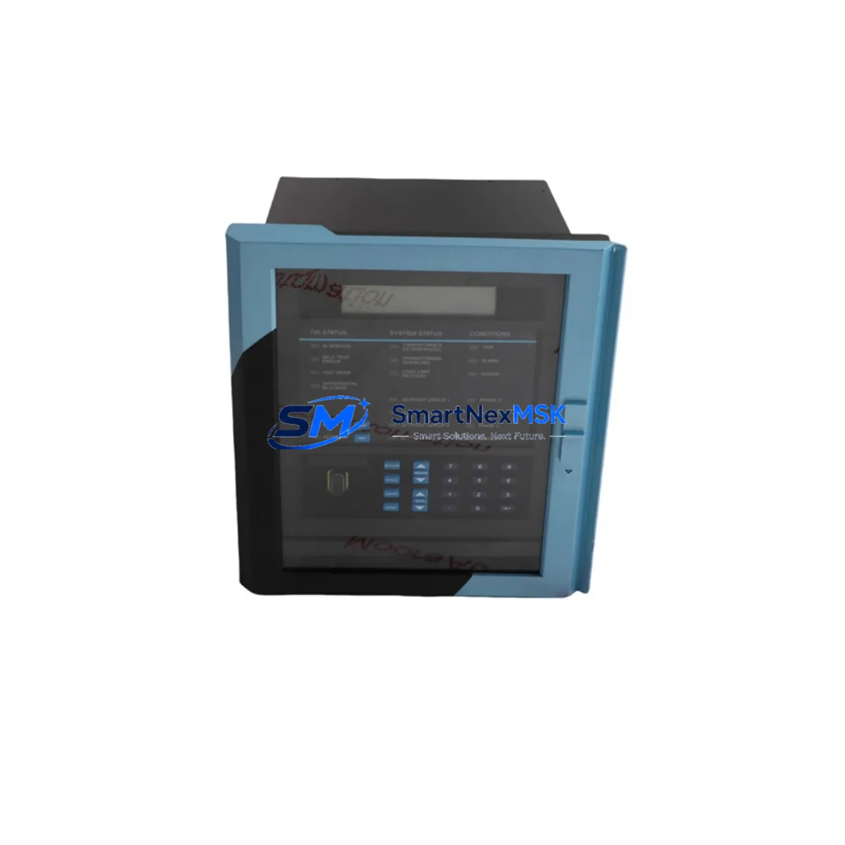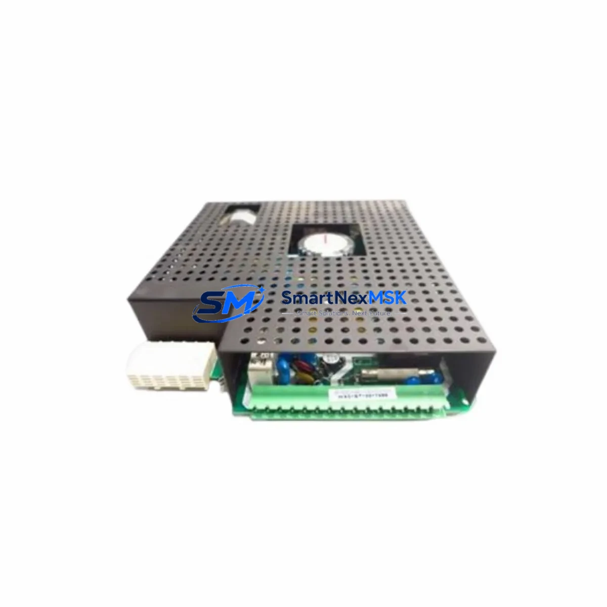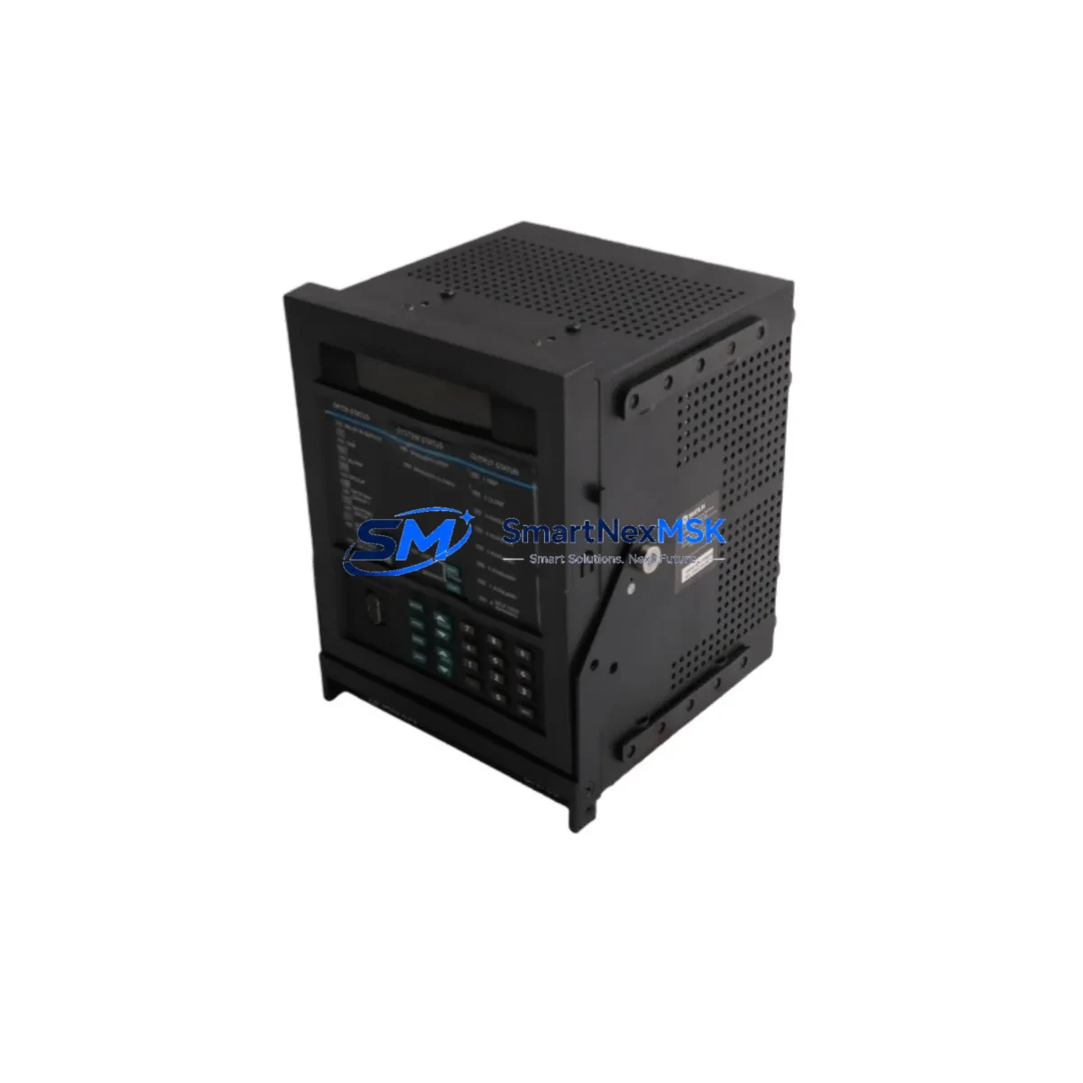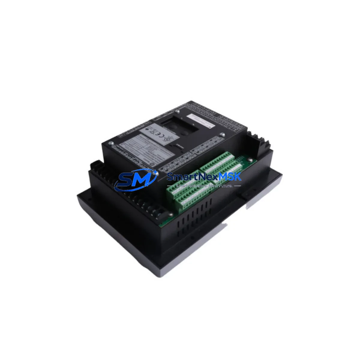
GE Multilin 369-HI-R-0-0-0-0-E Maintenance-Ready Spare for 369 Series Automation
The GE Multilin 369-HI-R-0-0-0-0-E is a high-impedance ground fault motor management relay from the GE Multilin 369 Series — one of the most widely deployed motor protection platforms in industrial automation environments worldwide. Designed for continuous-duty motor protection in pumping stations, compressor skids, conveyor drives, HVAC systems, and process plant motor control centers (MCCs), this relay delivers comprehensive protection functions including thermal overload, phase unbalance, ground fault, and locked rotor detection in a single compact unit.
For maintenance engineers managing aging motor control infrastructure, the 369-HI-R-0-0-0-0-E represents a direct, drop-in replacement for failed or end-of-life 369 Series relays. Its high-impedance ground input configuration makes it particularly suited for resistance-grounded or high-resistance grounded (HRG) distribution systems where sensitive ground fault detection is critical to preventing catastrophic motor failures and unplanned production shutdowns.
At SMARTNEXMSK, every 369-HI-R-0-0-0-0-E unit is sourced from verified supply channels, functionally tested prior to dispatch, and shipped with a 12-month warranty. We maintain ready stock to support emergency replacement orders, planned turnaround maintenance, and long-term spare parts inventory programs for facilities operating GE Multilin 369 Series protection systems.
Spare Maintenance Table
| Parameter | Specification / Detail |
|---|---|
| Part Number / SKU | 369-HI-R-0-0-0-0-E |
| Brand | GE Multilin (Grid Solutions) |
| Series | 369 Motor Management Relay Series |
| Product Type | Motor Management / Protection Relay |
| Ground Input Type | High-Impedance (HI) Ground Fault Input |
| Relay Output | Electromechanical (R-type output relay) |
| Communication | Base model — no optional comm module (0-0-0-0 suffix) |
| Power Supply | Standard control power input (per 369 Series spec) |
| Mounting | Panel / MCC door mount, standard 369 cutout |
| Protection Functions | Thermal overload, phase unbalance, ground fault (HI), locked rotor, undercurrent, phase reversal |
| Application Environment | Industrial MCC, pump stations, compressor skids, process plants |
| Compatibility | Direct replacement for GE Multilin 369 Series variants |
| Origin | USA |
| Condition | Original / New |
| Pre-shipment Testing | Functional test performed before dispatch |
| Warranty | 12 Months |
| Lead Time | In stock — ships within 1–3 business days |
Maintenance Planning for Continuous Operation
When replacing a 369-HI-R-0-0-0-0-E in the field, a thorough inspection of the surrounding motor control circuit is essential to ensure the root cause of relay failure is identified and that the replacement unit is not immediately exposed to the same fault conditions. Maintenance engineers should treat this replacement as an opportunity to audit the entire motor protection loop.
Begin with the control power supply feeding the relay — verify that input voltage is within the 369 Series rated range and that there are no voltage sags or transients caused by upstream switching. A failing or undersized control power transformer is a common but overlooked cause of relay malfunction. Inspect the current transformer (CT) wiring connected to the relay’s phase and ground CT inputs; loose or corroded CT secondary connections can introduce measurement errors that trigger nuisance trips or mask real fault conditions.
Check the ground CT or zero-sequence CT used with the high-impedance input — the 369-HI variant is specifically designed for use with a dedicated ground CT in HRG systems, and a mismatched or degraded CT will compromise ground fault sensitivity. While the cabinet is open, inspect the motor starter contactor and its auxiliary contacts, which feed run-status and trip-circuit feedback to the relay. Worn contactor tips or chattering auxiliary contacts are a frequent source of spurious relay events in aging MCCs.
For facilities running GE Multilin 369 Series relays across multiple motor feeders, it is good practice to maintain a small buffer stock of 369-LO-R-0-0-0-0-E (low-impedance ground variant) and 369-HI-R-0-0-0-0-E units to cover both grounding system configurations. Additionally, review the condition of the terminal blocks and wiring ferrules in the relay compartment — these are often overlooked during routine inspections but are a primary source of intermittent connection faults in high-vibration environments.
If the motor feeder includes a GE Multilin 469 Motor Management Relay or a 750/760 Series feeder protection relay on adjacent feeders, cross-check the protection coordination settings to ensure that the 369 replacement does not introduce coordination gaps. For systems with Modbus RTU or DeviceNet communication requirements, confirm whether the replacement unit requires an optional communication module — the base 369-HI-R-0-0-0-0-E does not include a comm card, and a 369-HI-R-M-0-0-0-E (Modbus variant) may be required if SCADA integration is in use.
Finally, inspect the motor thermistor input wiring if the motor is equipped with embedded PTC thermistors — the 369 Series supports thermistor-based thermal protection as a supplement to its internal thermal model, and a broken thermistor circuit will generate a fault on startup. Verify the output relay wiring to the trip coil and alarm circuits before energizing the replacement unit, and confirm that the relay settings (FLA, CT ratio, ground pickup threshold) are correctly programmed to match the motor nameplate and system protection philosophy.
Site Replacement Workflow
Step 1 — Isolation & Lockout/Tagout: De-energize the motor feeder and apply LOTO per site safety procedures. Verify absence of voltage on the motor terminals and control power bus before opening the MCC compartment.
Step 2 — Document Existing Settings: Before removing the failed 369-HI-R-0-0-0-0-E, record all relay settings via the front panel keypad or download the settings file via the RS-232 port if a laptop and GE EnerVista 369 PC software are available. This ensures the replacement unit can be programmed identically without referencing paper records.
Step 3 — Physical Removal: Disconnect all wiring from the relay terminals, labeling each wire with its terminal designation. Remove the relay from the panel cutout. Inspect the cutout gasket and panel surface for corrosion or moisture ingress.
Step 4 — Install Replacement Unit: Mount the new 369-HI-R-0-0-0-0-E into the panel cutout. Reconnect all wiring per the original terminal designations, verifying CT polarity and ground CT connection. Torque all terminals to specification.
Step 5 — Program & Commission: Restore relay settings from the saved file or re-enter manually. Verify CT ratio, FLA, ground pickup threshold, and trip/alarm relay assignments. Perform a trip circuit continuity test before re-energizing.
Step 6 — Energize & Verify: Restore control power and verify relay self-test passes with no active faults. Start the motor under supervision and confirm that metered current values match expected load. Log the replacement in the site maintenance management system (CMMS).
This workflow minimizes downtime to typically under 2 hours for a prepared maintenance team, restoring motor protection and production continuity with a verified, warranty-backed replacement unit.
Spare Parts Support FAQ
Q1: Is the 369-HI-R-0-0-0-0-E a direct drop-in replacement for other 369 Series variants?
The 369-HI-R-0-0-0-0-E is mechanically and electrically compatible with other GE Multilin 369 Series relays sharing the same panel cutout dimensions. However, the HI (high-impedance) ground input configuration is specific to HRG or resistance-grounded systems. If your existing installation uses a low-impedance ground CT, you may require the 369-LO variant. Always verify the ground input type against your system’s grounding configuration before ordering.
Q2: How do you verify compatibility before shipment?
Each unit undergoes a pre-shipment functional test covering power-up self-test, output relay operation, and input circuit continuity. We cross-reference the SKU suffix against the GE Multilin 369 Series ordering guide to confirm the correct hardware configuration. A test report is available upon request for critical applications.
Q3: What does the 12-month warranty cover?
The 12-month warranty covers manufacturing defects and functional failures under normal operating conditions from the date of shipment. It does not cover damage resulting from incorrect installation, overvoltage events, or physical mishandling. In the event of a warranty claim, we provide a replacement unit or full refund after fault verification.
Q4: Can you support long-term spare parts programs for facilities with multiple 369 Series relays?
Yes. We support blanket purchase orders, scheduled delivery programs, and dedicated inventory reservation for facilities managing large populations of GE Multilin 369 Series relays. Contact our technical sales team to discuss volume pricing, lead time commitments, and consignment stock arrangements tailored to your maintenance planning cycle.
© 2026 SMARTNEXMSK. All rights reserved.
Original Source: https://smartnexmsk.com
Contact: [email protected] | +86 18259474341