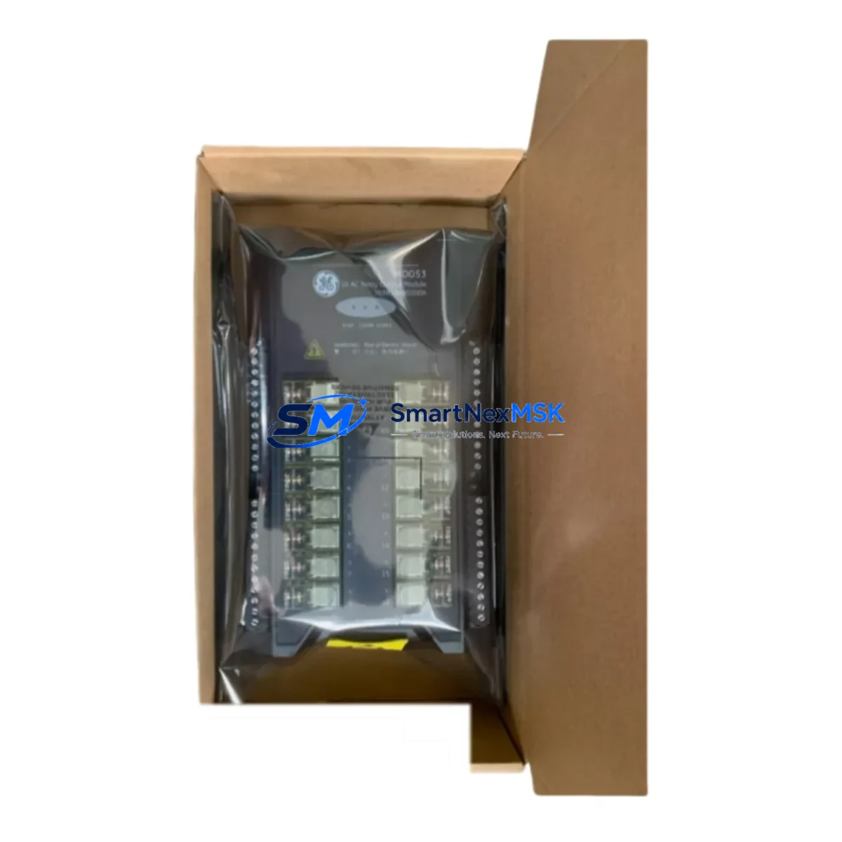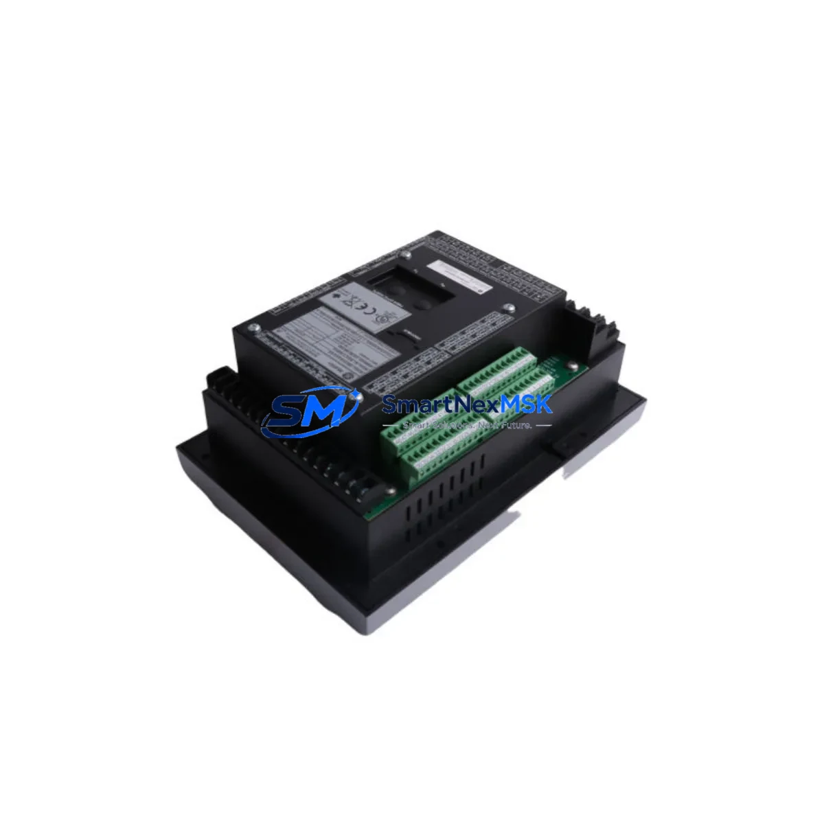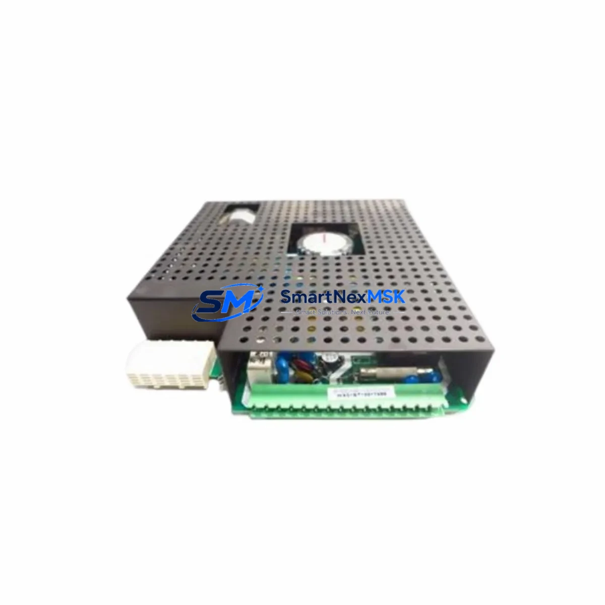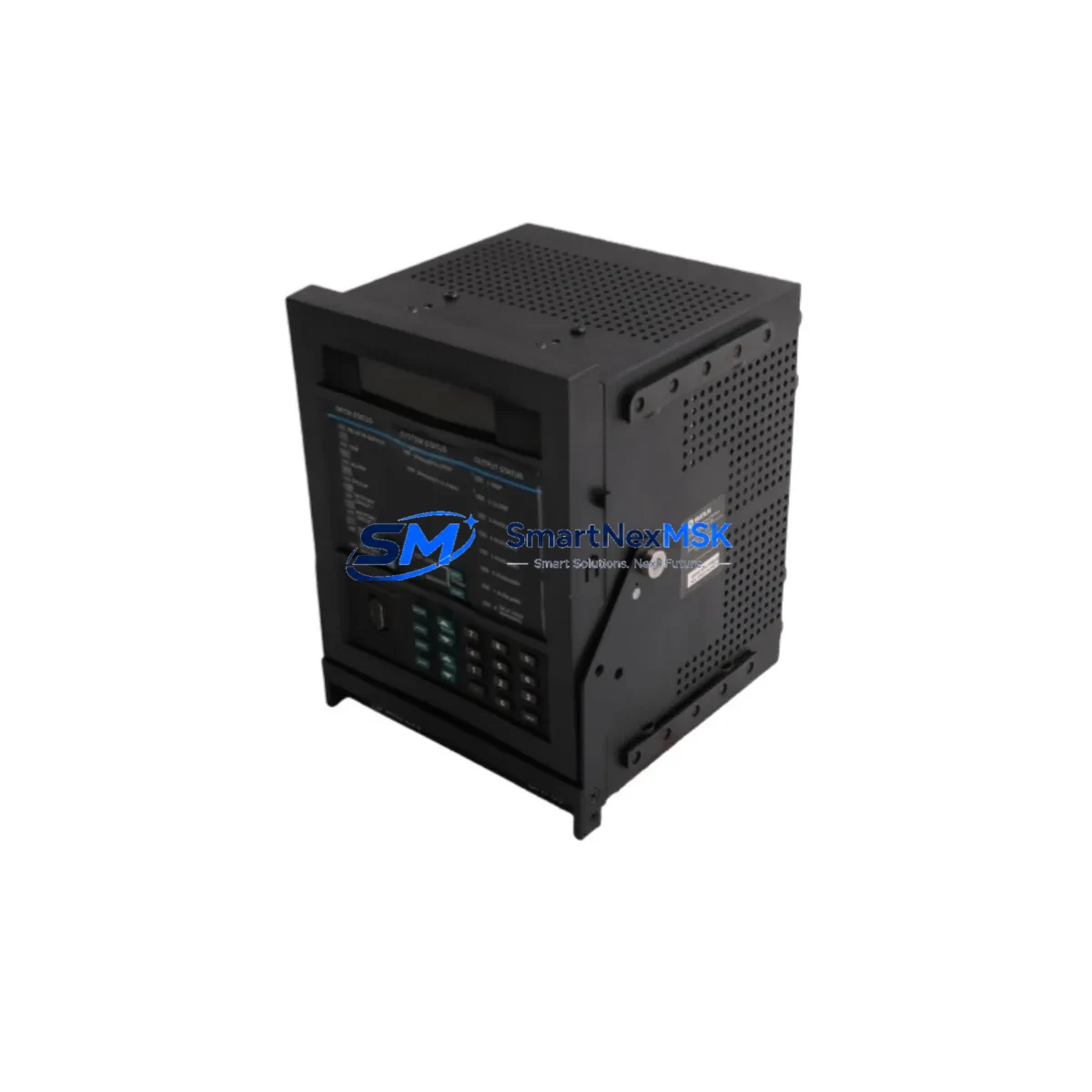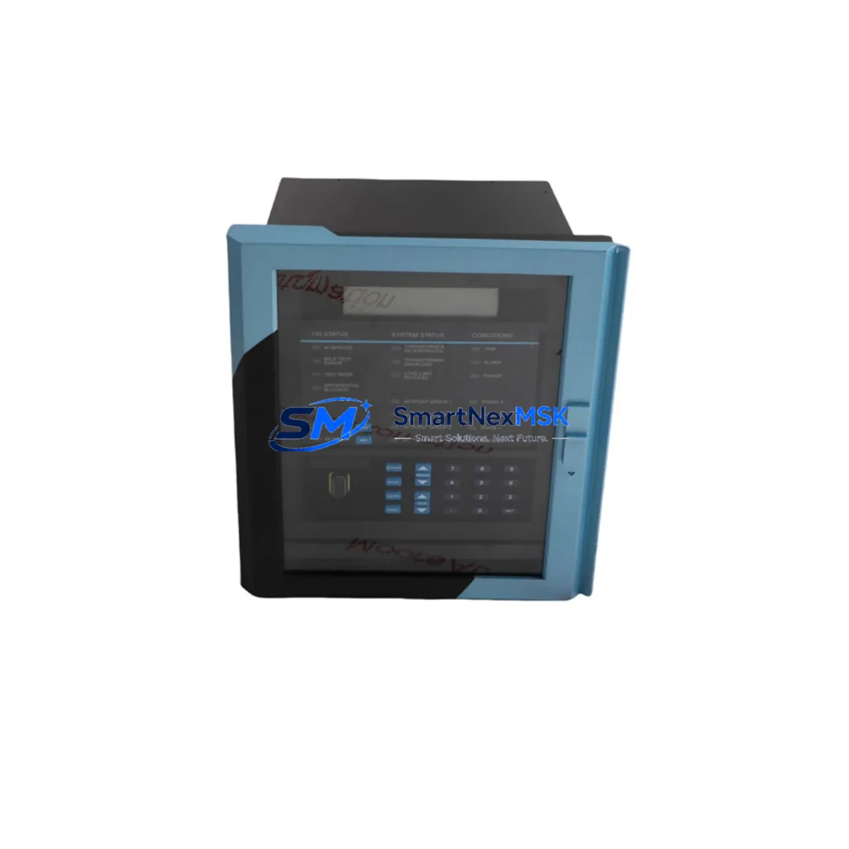
GE Multilin 745-W2-P5-G5-HI-R-E-H Retrofit-Ready Transformer Protection Relay for 745 Series Control Systems
The GE Multilin 745-W2-P5-G5-HI-R-E-H is a full-featured transformer protection relay engineered for the 745 Series platform. As aging protection systems reach end-of-life or become increasingly difficult to maintain, this unit serves as a verified retrofit-ready replacement for facilities operating legacy GE Multilin transformer protection schemes. Whether you are managing a planned upgrade cycle or responding to an unplanned failure of a discontinued relay, the 745-W2-P5-G5-HI-R-E-H delivers the compatibility, configurability, and reliability required for continuous transformer protection in critical power distribution environments.
This relay supports dual-slope percentage differential protection, overcurrent elements, restricted earth fault (REF), overexcitation (V/Hz), and thermal modeling — making it suitable for two-winding and three-winding power transformer applications in industrial substations, utility feeders, and process plant MV/HV switchgear. The W2 winding configuration, P5 protection package, G5 communications option, HI high-impedance input, R rear terminal block, E Ethernet port, and H high-speed output relay options are factory-configured and tested prior to shipment.
Upgrade Compatibility Table
| Parameter | Details |
|---|---|
| SKU / Model | 745-W2-P5-G5-HI-R-E-H |
| Series | GE Multilin 745 Series |
| Winding Configuration | Two-Winding (W2) |
| Protection Package | P5 — Full differential, overcurrent, REF, V/Hz, thermal |
| Communications | G5 — Modbus RTU, DNP3, IEC 61850 GOOSE (Ethernet) |
| Input Type | HI — High-impedance analog inputs |
| Terminal Block | R — Rear-mounted screw terminals |
| Ethernet Port | E — RJ45 rear Ethernet |
| Output Relay Type | H — High-speed output relays |
| Mounting | 19″ rack / panel flush mount, standard 745 Series cutout |
| Retrofit Compatibility | Direct replacement for GE Multilin 745 Series variants; compatible terminal footprint with R-suffix models |
| Communication Protocol Migration | Supports Modbus RTU → IEC 61850 migration without panel rewiring |
| Commissioning Requirement | Settings file import via EnerVista 745 Setup software; CT/VT ratio verification required |
| Warranty | 12 Months — covers hardware defects, output relay contacts, and communications ports |
Retrofit Planning for Existing Automation Systems
Replacing a legacy transformer protection relay in an operating substation or process plant requires careful pre-engineering to avoid configuration mismatches and extended outages. When migrating from an older GE Multilin 745 variant or a third-party relay to the 745-W2-P5-G5-HI-R-E-H, engineers should begin by auditing the existing panel wiring against the rear terminal block layout of the R-suffix model. The screw terminal arrangement on R-suffix 745 units is consistent across the product generation, which significantly reduces rewiring scope compared to cross-brand replacements.
Power supply capacity is a critical first checkpoint. The 745-W2-P5-G5-HI-R-E-H accepts a wide-range DC auxiliary supply (typically 24–250 VDC), but the existing panel power distribution board or DC UPS must be verified to supply adequate current under relay startup inrush. If the control cabinet houses a GE Multilin EPM 7000 power meter or a 369 Motor Management Relay sharing the same DC bus, load calculations should account for simultaneous energization during restoration after a planned outage.
CT and VT secondary wiring must be confirmed before removal of the existing relay. The 745-W2-P5-G5-HI-R-E-H uses standard 1A or 5A CT inputs; if the legacy installation used a non-standard ratio or a different burden class, interposing CTs may be required. Winding polarity markings on the transformer bushings should be cross-referenced against the differential element’s CT polarity settings in the EnerVista 745 Setup configuration file. Incorrect polarity will cause the differential element to operate on load current — a critical commissioning error that must be caught during secondary injection testing before energization.
For facilities running SCADA or DCS integration via Modbus RTU over RS-485, the G5 communications option on this relay supports both Modbus RTU and DNP3 on the serial port simultaneously with IEC 61850 over the rear Ethernet port. This allows a phased protocol migration: the existing Modbus RTU link to a GE iFIX SCADA node or a Wonderware InTouch HMI station can remain active while the IEC 61850 GOOSE configuration is commissioned in parallel. This dual-protocol capability is particularly valuable in substations where the RTU — such as a GE D20MX or a Schweitzer SEL-3530 — is being upgraded concurrently.
I/O mapping is another area requiring careful pre-planning. The 745-W2-P5-G5-HI-R-E-H provides multiple configurable output relay contacts and optoisolated digital inputs. If the existing relay drove a lockout relay (86T) or a breaker trip coil directly, the output contact ratings must be verified against the trip coil burden. The H-suffix high-speed output relays on this unit are rated for high-current interruption, making them suitable for direct trip applications without an interposing relay. Digital inputs used for breaker status, transformer tap position, or OLTC control signals should be mapped in the settings file before the relay is installed in the panel.
Backplane and rack considerations apply when the 745 is installed in a multi-relay protection panel alongside units such as a GE Multilin 489 Generator Management Relay, a 750/760 Feeder Protection Relay, or a 650 Series bay controller. Ensure that the panel rack has adequate depth for the rear terminal block and that cable management allows for the Ethernet patch cable to the station LAN switch without sharp bends. If the panel also houses a GE Multilin 1200 Series current transformer test switch or a shorting terminal block for CT secondary isolation, confirm that the test switch is in the correct position before secondary injection.
Downtime Control During System Migration
Minimizing transformer outage duration during relay replacement is a primary concern for plant maintenance teams and substation operators. A structured pre-outage preparation process is the most effective way to compress the maintenance window. Before the scheduled outage, the replacement 745-W2-P5-G5-HI-R-E-H should be bench-tested with the actual settings file exported from the existing relay (or a newly prepared settings file if the original is unavailable). Bench testing should include secondary injection of differential, overcurrent, and REF elements to verify pickup and timing values match the protection coordination study.
The existing relay’s event log and fault records should be downloaded via the EnerVista 745 Setup software or the front panel RS-232 port before removal. These records provide a baseline for post-commissioning comparison and may be required for insurance or regulatory documentation. If the relay communicates to a GE Multilin SR3 or a third-party IED gateway, the communication session should be terminated cleanly before the relay is de-energized to avoid gateway alarm floods.
During the physical swap, the rear terminal block wiring should be photographed and labeled before any terminals are loosened. Use a systematic terminal-by-terminal approach, transferring wiring in groups (CT circuits, VT circuits, DC supply, output contacts, digital inputs, communications) rather than removing all wiring at once. This approach allows the commissioning engineer to verify each circuit group against the wiring diagram before moving to the next, reducing the risk of cross-wiring errors that would extend the outage.
After installation, the commissioning sequence should follow the relay’s standard energization procedure: apply auxiliary supply first, verify relay self-test passes, then apply CT and VT circuits with the transformer isolated. Perform a secondary injection test on the differential element before closing the transformer breaker. Once the transformer is energized, monitor the relay’s metering screens for correct current and voltage readings, verify differential current is within the restraint region under load, and confirm SCADA communication is re-established. A complete commissioning record — including injection test results, settings file version, and communication test confirmation — should be archived for the asset management system.
Retrofit Support FAQ
Q1: Is the 745-W2-P5-G5-HI-R-E-H a direct drop-in replacement for my existing GE Multilin 745 relay?
For R-suffix (rear terminal block) 745 Series variants, the physical terminal layout is compatible, and the panel cutout dimensions are identical across the 745 product generation. Settings files from earlier 745 firmware versions can be imported into the replacement unit using EnerVista 745 Setup software, though a settings review is recommended to confirm that any deprecated function codes have been remapped correctly. Units with different suffix combinations (e.g., different winding configurations or protection packages) may require settings adjustments before commissioning.
Q2: What communications protocols does this relay support, and can I migrate from Modbus RTU to IEC 61850 without rewiring?
The G5 communications option supports Modbus RTU and DNP3 on the rear RS-485 serial port and IEC 61850 Edition 1/2 over the rear RJ45 Ethernet port. Both protocols can operate simultaneously, allowing a phased migration from legacy serial SCADA to IEC 61850-based substation automation without panel rewiring. The IEC 61850 logical node configuration is performed via the EnerVista 745 Setup software and requires a station-level SCL file exchange with the substation automation system.
Q3: What pre-shipment testing is performed, and what does the 12-month warranty cover?
Each 745-W2-P5-G5-HI-R-E-H unit undergoes functional testing of protection elements, output relay contacts, digital inputs, and communications ports prior to shipment. The 12-month warranty covers hardware defects in the relay chassis, output relay contacts, analog input circuits, and communications interfaces under normal operating conditions. Warranty claims are supported with a return merchandise authorization (RMA) process; a replacement unit can be dispatched in advance of the defective unit’s return to minimize site downtime.
Q4: Can this relay be used to replace a non-GE transformer protection relay, and what additional engineering is required?
Cross-brand replacement is feasible but requires a full terminal-by-terminal wiring adaptation study, since terminal layouts and CT/VT circuit conventions differ between manufacturers. A new settings file must be prepared from the protection coordination study rather than imported from the legacy relay. Secondary injection testing of all protection elements is mandatory before energization. Our technical team can provide application support for cross-brand retrofit projects, including terminal mapping assistance and settings file preparation guidance.
© 2026 SMARTNEXMSK. All rights reserved.
Original Source: https://smartnexmsk.com
Contact: [email protected] | +86 18259474341